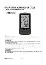
background image

25

SB900 

INDOOR CYCLE


3-IN-ONE Oil or 10W

oil. Do not use 
silicone-based 

lubricants


Inspect for excessive  wear or

a dry leather brake pad


TROUBLESHOOTING


No Display on Console 

1.  Press any key to bring the console to ‘Quick Start’ mode. 
2.  Ensure the battery icon is not shown on the Console and transmitter have batteries installed 

properly. Red LED light will flash on the transmitter when battery is low. 

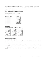
RPM or HR does not change 

1.   Press ‘MODE key’ repeatedly to toggle between SPEED (SPD), DISTANCE (DIST), TIME (TIME) 

and CLOCK (CLK) values. 

2.   Holding ‘PAGE key’ to clear past measured value or go into setting and exit. 

Cadence number jumps high or low 

1.  Separate bikes may be paired to same console and are cross-talking, simply run transmitter 

pair stage again on the bike. 

2.  Relocate the bike to a different part of the room, away from any RF interference areas. 

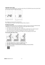
Heart Rate signal gets interrupted or drops out 

1.  Ensure that there is a minimum distance of 36 inches between bikes. 
2.  Make sure your Bluetooth HR monitor is secure and electrodes are making contact with your 

chest at all times. 

No Heart Rate signal displayed


1.   Ensure your Bluetooth HR monitor is worn correctly, and there is moist under electrodes of the 

Bluetooth HR monitor. 

CAUTION 

EXTERNAL INTERFERENCE MAY BE CAUSED BY OTHER ELECTRONIC DEVICES, SUCH AS: 
NEARBY TELEVISIONS, STEREO EQUIPMENT, SPEAKERS, ELECTRICAL WIRE CABLING, ETC. IF 
YOU EXPERIENCE DISTURBANCES IN CONSOLE DISPLAY TRY MOVING YOUR BIKE (S) AWAY 
FROM POTENTIAL RF INTERFERENCE AREAS. 
RELOCATE THE BIKE AWAY FROM ANY EQUIPMENT THAT COULD POTENTIALLY INTERRUPT 
THE RADIO FREQUENCY SIGNAL, SUCH AS A DVD PLAYER OR TELEVISION, ETC. 


MAINTENANCE GUIDELINES


MAINTENANCE SCHEDULE 


PART RECOMMENDED 

ACTION 

FREQUENCY

CLEANER 

LUBRICANT 

Pedals Ensure 

that 

pedals 

are 

tight 

in 

crank arms; that all screws on 

pedals are tight; and that the 

pedal straps are not frayed 

Before  each 

use 

N/A 

N/A 

Frame 

Wipe down by using a soft 

damp clean cloth 

Daily 

Water 

N/A 

Flywheel Wipe 

down 

by 

spraying 

on 

rag and applying a light coat 

to sides of the flywheel 

Weekly 

WD-40 

spray. 

N/A 

Brake 

Pad 

Inspect for excessive wear 

or squealing 

Weekly 

N/A 

Silicone  Spray 


1.    Do not service internal parts of pedals. If they are found to be worn internally, we 

recommend replacing the pedal. 

2.    Use of lubricants or cleaning solutions other than those so specified will result in 

diminished performance and a shorter life span for that part. 

Summary of Contents for SB900

Page 1: ...OWNERÊS MANUAL PLEASE CAREFULLY READ THIS ENTIRE MANUAL BEFORE OPERATING YOUR NEW INDOOR CYCLE ...

Page 2: ...900 Assembly Instructions 5 Operation of Your New Indoor Cycle 11 Exploded View Drawing 27 Parts list 28 ATTENTION THIS FITNESS BIKE IS INTENDED FOR RESIDENTIAL USE ONLY AND IS WARRANTED FOR THE APPLICATION ANY OTHER APPLICATION VOIDS THIS WARRANTY IN ITS ENTIRETY SB900CGS 3268_2009 SL A ...

Page 3: ... up handlebar post and seat post over the MAX graduation 11 For safe operation allow for at least 1foot 30cm of free space to either side of the unit and 2 feet 60cm of free space to the rear of the unit Regularly examine the bike for damage and wear Inoperable components should be replaced immediately or the equipment should not be used until it is repaired Failure to follow all guidelines may co...

Page 4: ...3 8 x 3 1 2 Carriage Bolt 4 pcs 83 3 8 x 23mm Curved Washer 4 pcs 2HARDWARESTEP2 91 M5 x 10mm Phillips Head Screw 2 pcs 4HARDWARESTEP4 48 5 16 x 16 x1T Flat Washer 4 pcs 88 M8 P1 25 20L Button Head Socket Bolt 4 pcs 143 5 16 15L Button Head Socket Bolt 4 pcs 144 5 16 7T Nylon Nut 4 pcs ...

Page 5: ...5 SB900 INDOOR CYCLE 6HARDWARESTEP6 ASSEMBLY TOOLS 101 4 16mm_ Sheet Metal Screw 3 pcs 85 14 15m m_Wrench 86 M5_Combination M5 Allen Wrench Phillips Head Screw Driver 145 13 14m m_Wrench ...

Page 6: ...ardware package Remove the tools first Remove the hardware for each step as needed to avoid confusion The numbers in the instructions that are in parenthesis are the item number from the assembly drawing for reference 1STABILIZERTUBES 1 Install the front and rear stabilizers with four Carriage Bolts 81 four Curved Washers 83 and four Nuts 82 The front and rear stabilizer are different Be sure to a...

Page 7: ...R CYCLE 2 REAR STABILIZER COVER HARDWARE STEP 2 91 M5 x 10mm Phillips Head Screw 2 pcs 1 Install the rear stabilizer cover with two Phillips Head Screws 91 3CONSOLE 1 Console 2 Clamp mounting screw 3 Mounting Clamp ...

Page 8: ...ing Handlebar Mount 8 with four M8 P1 25 20L Button Head Socket Bolts 88 four 5 16 16 1T_Flat Washers 48 Tighten the bolts securely by using the M5_ Combination M5 Allen Wrench Phillips Head Screw Driver 86 2 Install the Drink Bottle Holder L 141 and Drink Bottle Holder R 142 with four 5 16 15L_Button Head Socket Bolt 143 and four 5 16 7T_Nylon Nut 144 by using the M5_Combination M5 Allen Wrench P...

Page 9: ...l the Left 25L and Right 25R pedals to the crank arms Please note that the Left pedal has a reverse threaded bolt and needs to be tightened in a counterclockwise direction The pedals are identified by either an R or L stamped into the end of the bolt ...

Page 10: ...3 2 Without removing the transmitter from the left cover 112 remove the Battery Cover from the transmitter 3 Install 2 AAA batteries in the battery compartment and reinstall the battery cover 4 When new batteries are installed in the transmitter or console you must perform the synchronizing procedure below for the console to work properly 5 After synchronizing make sure the wire from transmitter i...

Page 11: ...nize the two so they can talk to each other 1 Press and hold the two keys on the front of the console for about 3 seconds until the display shows ID 2 Now press and hold the blue button on the transmitter for 3 seconds and release The console display should show ID 0 NOTE You must press the blue button within 10 seconds after the console is showing ID otherwise the console will show ID ER If the c...

Page 12: ...o be displayed MPH KPH in this section In addition to MPH KPH CADENCE will also display a bar graph allow riders to keep track of approximate cadence Average Cadence or Speed will be automatically shown after rider stop pedaling for 3 seconds DISTANCE Distance is measurement of the approximate distance achieved on the bike This distance is calculated based on user riding a bike with tires having s...

Page 13: ...e Power Saving Mode Quick Start Mode MODE SELECT Press MODE key to select TIME DIST KCAL display RESETTING ALL MEASURED VALUE To clear all measured values press and hold Page key under TIME Mode for 3 seconds All measured value AVG SPEED AVG PULSE TIME DIST KCAL will reset TIMER SETTING TIMER displays user s workout duration If the user does not set the COUNT DOWN TIME TIMER will count up from 00 ...

Page 14: ...for 3 seconds to go into setting continuously key to get to heart rate windows 1 Press Page key to select gender either Male Female 2 Press Page key to go to weight unit settings Press Mode key to select weight Kg Lb Note change of metric units to imperial units will affect all displaying units MPH KPH Lb KG and ML KM 3 Press Page key will go to weight settings Press Mode key to increase weight by...

Page 15: ...15 SB900 INDOOR CYCLE 1 Log in to Zwift 2 Select power source and cadence system will prompt you to select machine 3 ...

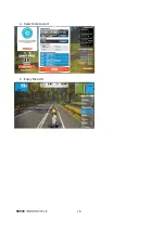
Page 16: ...SB900 INDOOR CYCLE 16 4 Select ride to start 5 Enjoy the ride ...

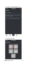
Page 17: ...17 SB900 INDOOR CYCLE 1 Select More on the bottom right corner 2 Select equipment management ...

Page 18: ...SB900 INDOOR CYCLE 18 3 Select on the top right corner 4 Select exercise bike ...

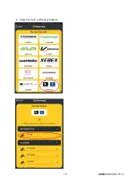
Page 19: ...19 SB900 INDOOR CYCLE 5 Select sensor at the very bottom 6 Select FTMS ...

Page 20: ...SB900 INDOOR CYCLE 20 7 Select machine you wish to connect 8 Successfully paired machine will show up on this page ...

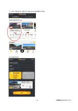
Page 21: ...21 SB900 INDOOR CYCLE 9 Go to browse to select a video you would like to play 10 Select start ...

Page 22: ...SB900 INDOOR CYCLE 22 11 Press start on the console when kinomap ask you to start pedaling 12 Enjoy the ride This console is compatible with most virtual active apps available ...

Page 23: ...inal position mark on the seat post for future reference Seat Forward Aft Adjustment 8 Sit on the bike with the crank arms in the 3 and 9 o clock positions A proper forward aft position for road bike training of the seat is achieved when the small bump at the top of your shin is above the pedal axle 9 Dismount the bike Loosen the quick release under the seat and slide the seat forward or backward ...

Page 24: ...or to tighten the strap depress the spring loaded clasp then pull on the open end of the nylon strap until the strap is snug around each foot USING THE CLEAT PEDALS Engage cleated shoes in pedals by placing cleat between bindings while pushing down Disengage by twisting heel outwards away from exercise bike Binding tension is adjustable and should be set so that cleat and shoe do not disengage whe...

Page 25: ...splayed 1 Ensure your Bluetooth HR monitor is worn correctly and there is moist under electrodes of the Bluetooth HR monitor CAUTION EXTERNAL INTERFERENCE MAY BE CAUSED BY OTHER ELECTRONIC DEVICES SUCH AS NEARBY TELEVISIONS STEREO EQUIPMENT SPEAKERS ELECTRICAL WIRE CABLING ETC IF YOU EXPERIENCE DISTURBANCES IN CONSOLE DISPLAY TRY MOVING YOUR BIKE S AWAY FROM POTENTIAL RF INTERFERENCE AREAS RELOCAT...

Page 26: ...SB900 INDOOR CYCLE 26 EXPLODED VIEW DIAGRA ...

Page 27: ...1 Aluminum Locking V Blocks 36 31 19 5L 2 22 Latch Ø11 8 7L 2 25 Pedal Set 25L 25R 1 27 Seat 1 29 5 16L_Tapping Screw 1 30 3 5 12L_Sheet Metal Screw 11 31 Flywheel 1 32 Bearing Housing 2 33 Flywheel Axle 1 34 Woodruff Key 1 35 Flywheel Pulley 1 36 5 16 UNC18 3 4 _Button Head Socket Bolt 1 37 Ø8 Ø20 3T_Flat Washer 1 38 5 16 UNC18 3 4 _Button Head Socket Bolt 6 39 M6 P1 0 10L_Flat Phillips Head Scre...

Page 28: ...ly Optional 1 78 Ø8 Ø23 2 0T_Flat Washer 1 79 Ø10 Ø19 1 5T_Flat Washer 2 80 M10 P1 25 10T_Nut 2 81 3 8 UNC16 3 1 2 _Carriage Bolt 4 82 3 8 UNC16 12 5T_Cap Nut 4 83 Ø10 Ø23 1 5T_Curved Washer 4 85 14 15m m_Wrench 1 86 M5_Combination M5 Allen Wrench Phillips Head Screw 1 87 Drink Bottle Optional 1 88 M8 P1 25 20L_Button Head Socket Bolt 4 89 M5 P0 8 10L_Socket Head Cap Screw 4 90 Ø5 10L_Tapping Scre...

Page 29: ...20L_Button Head Socket Bolt 1 131 M6 P1 0 50L_Hex Head Bolt 1 132 M6 P1 0 5 0T_Luck Nut 2 133 Cable Fix 1 134 Brake Pad Wool Felt 2 135 Cable Hook 2 136 Rubber Pad Ø17 5 Ø23 5 0 3T 1 137 5 16 UNC18 5 8 _Button Head Socket Bolt 5 138 Tablet Holder Bottom 1 138 1 Tablet Holder Adjustable Clip 1 138 2 Tablet Holder Front 1 140 Fixing Plate 1 141 Drink Bottle Holder L 1 142 Drink Bottle Holder R 1 143...

Reviews: