


Chapter 7: Setting Up Communication
SolarEdge Installation Guide – MAN-01-00002-1.7
48
8
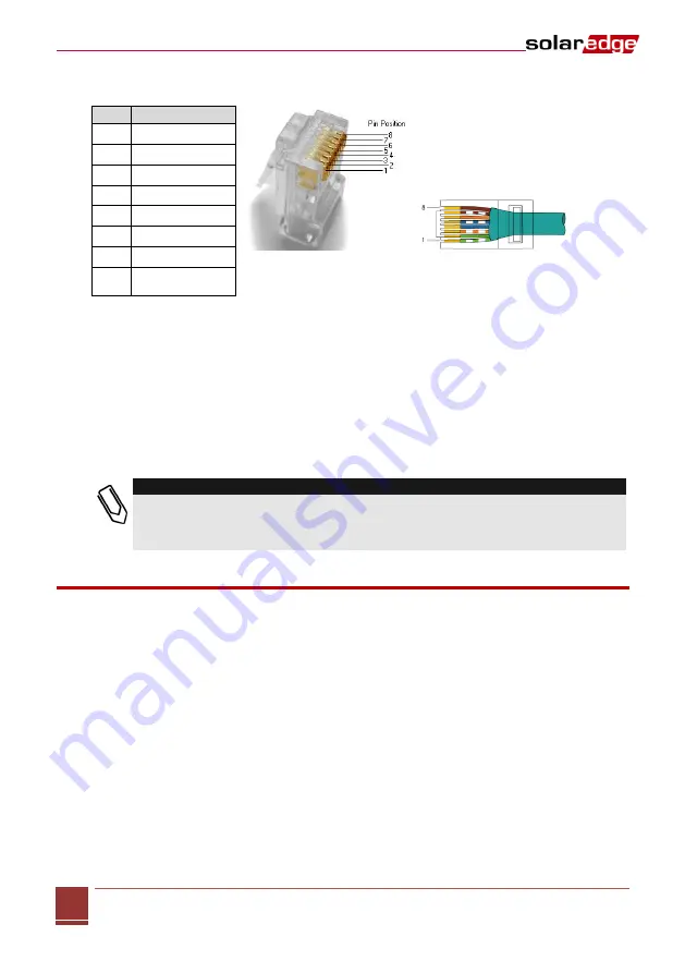
For the switch/router side, use a pre-crimped cable or use a crimper to prepare an RJ45
communication connector: Insert the eight wires into the RJ45 connector.
Pin
Wire Color
1
White/green
2
Green
3
White/Orange
4
Blue
5
White/Blue
6
Orange
7
White/Brown
8
Brown
Figure 33: Inserting Wires into the RJ45 Connector
9
Connect the cable’s RJ45 connector to the RJ45 port of the Ethernet switch or router. You can
connect more than one inverter to the same switch/router or to different switches/routers, as
needed. Each inverter sends its monitored data independently to the SolarEdge monitoring portal.
All connections are initiated from the inverter so that no port forwarding is required.
10
Inverters are configured by default to
LAN
. If the inverter is being reconfigured to
LAN
, use the user
buttons to configure the connection, as described in
Communication on page 38
11
Close the inverter cover.
12
Verify the connection, as described in
Verifying the Connection
on page 51.
NOTE:
If your network has a firewall, then you may need to configure it to enable the connection to the
following address:
Destination Address: prod.solaredge.com
Port:
22222
Creating an RS485 Bus Connection
The RS485 option enables creating a bus of connected inverters, consisting of up to 30 slave inverters and
1 master inverter. Using this option, inverters are connected to each other in a chain, via their RS485
connectors. The first and last inverters in the chain must be terminated.
The following sections describe how to physically connect the RS485 bus and how to configure the bus.
►
To connect the RS485 communication bus:
1
Open the inverter cover.
2
Remove the seal from one of the openings in communication gland #2 and insert the wire through
the opening.


