


Chapter 7: Setting Up Communication
SolarEdge Installation Guide – MAN-01-00002-1.7
45
Chapter 7: Setting Up Communication
Power optimizers send information to the inverter via the DC power lines (the PV output circuit). No
additional wires or configurations are required for this purpose. The information is then sent from the
inverter to the SolarEdge monitoring portal through the Internet. In order to send the data from the
inverter, a communication connection must be set up, as described in this chapter. Communication setup
is not required for power harvesting and is needed only for using the SolarEdge monitoring portal.
This chapter also describes setting up communication between multiple inverters for a master/slave
configuration.
Communication Connectors
Two communication glands, each 20mm in diameter, are used for connection of the various inverter
communication options. Each gland has three openings. The table below describes the functionality of
each opening. Unused openings should remain sealed.
Gland#
Opening
Functionality
Cable Size (diameter)
1
One small
RS232
2-4 mm
Two large
Ethernet connection (CAT5/6) or ZigBee
4.5-7 mm
2
All three
RS485, power reduction
2.5-5 mm
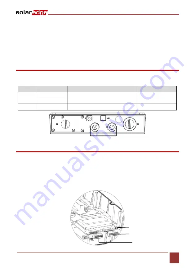
Figure 26: Communication Glands
Communication Types
Ethernet:
page 46, used for a LAN connection
RS485:
page 48, the most commonly used communication type, used for the connection of multiple
SolarEdge devices on the same bus in a master-slave configuration. RS485 type can also be used as
an interface to external non-SolarEdge devices, such as revenue meters and data loggers.
Optional wireless communication option:
ZigBee
Always connect the communication options when the inverter is OFF.
Figure 27: Internal Connectors
Mini USB
Ethernet
RS232/RS485


