Sokkia CX-62 Operator'S Manual Download Page 296

288

36. STANDARD EQUIPMENT AND OPTIONAL ACCESSORIES

Telescope eyepiece lens (EL7)

Magnification: 40X
Field of view: 1° 20'

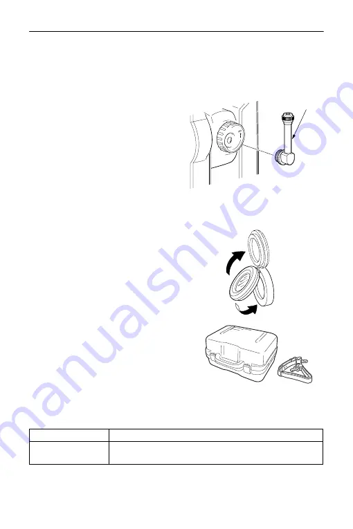
Diagonal eyepiece (DE27) 

The diagonal eyepiece is convenient 
for observations near the nadir and 
in narrow spaces.
Magnification: 30X

After removing the handle from the 
CX, loosen the attachment screw to 
remove the telescope eyepiece. 
Then screw the diagonal lens into 
place.

Handle removal method: 

"4.1 Parts of the Instrument"

Solar filter (OF3A)

When sighting targets where glare is 
present, solar observations for 
example, attach it to the objective 
lens of the CX to protect its interior 
and the eyes of the operator. The 
filter part can be flipped up without 
being removed.

Carrying case (SC249S)


Carrying strap

This is a carrying case and strap set. 
Attach the strap to the carrying case 
to shoulder the case.

Interface cable

Connect between the CX and the host computer for data output.

Cable

Notes

DOC210

Pin Numbers and signal levels : RS-232C compatible
D-sub connector

: 9pins (female)

DE27

Summary of Contents for CX-62

Page 1: ...SURVEYING INSTRUMENTS OPERATOR S MANUAL CX 62 CX 65 Compact X ellence Station CLASS 3R Laser Product 1016315 01 A ...

Page 2: ... This is the mark of the Japan Surveying Instruments Manufacturers Association Li ion S Li ion ...

Page 3: ...ions from a host computer can also be performed For details refer to Communication manual and ask your local dealer The specifications and general appearance of the instrument are subject to change without prior notice and without obligation by TOPCON CORPORATION and may differ from those appearing in this manual The content of this manual is subject to change without notice Some of the diagrams s...

Page 4: ... setting It is possible to change the allocation of softkeys in OBS mode What are softkeys 4 1 Parts of the Instrument Softkeys allocation 33 3 Allocating Key Functions Learn basic key operations in 5 BASIC OPERATION before you read each measurement procedure For selecting options and inputting figures see 5 1 Basic Key Operation Measurement procedures are based on continuous measurement Some info...

Page 5: ...ed Bluetooth device 42 10 3 Measurement using Bluetooth communication 45 10 4 Registering Outputting data using Bluetooth communication 46 10 5 Connecting via Communication Cable 48 11 ANGLE MEASUREMENT 49 11 1 Measuring the Horizontal Angle between Two Points Horizontal Angle 0 49 11 2 Setting the Horizontal Angle to a Required Value Horizontal Angle Hold 50 11 3 Angle Measurement and Outputting ...

Page 6: ...1 Single distance Offset Measurement 129 20 2 Angle Offset Measurement 131 20 3 Two distance Offset Measurement 133 20 4 Plane Offset Measurement 136 20 5 Column Offset Measurement 138 21 MISSING LINE MEASUREMENT 140 21 1 Measuring the Distance between 2 or more Points 140 21 2 Changing the Starting Point 145 22 SURFACE AREA CALCULATION 147 23 INTERSECTIONS 151 24 TRAVERSE ADJUSTMENT 155 25 ROUTE ...

Page 7: ...1 1 Outputting JOB Data to Host Computer 236 32 USING USB MEMORY DEVICE 240 32 1 Inserting the USB Memory Device 241 32 2 Storing JOB Data to USB Memory device 242 32 3 Selecting T type S type 242 32 4 Loading Data in USB memory device to the CX 245 32 5 Displaying and Editing Files 247 32 6 Formatting the Selected External Memory Media 248 33 CHANGING THE SETTINGS 250 33 1 Configuration Config Mo...

Page 8: ... 36 3 Target system 289 36 4 Power supplies 291 37 SPECIFICATIONS 292 38 EXPLANATION 298 38 1 Manually Indexing the Vertical Circle by Face 1 2 Measurement 298 38 2 Correction for refraction and earth curvature 300 39 REGULATIONS 301 ...

Page 9: ...s main text Definition of Indication WARNING Ignoring this indication and making an operation error could possibly result in death or serious injury to the operator CAUTION Ignoring this indication and making an operation error could possibly result in minor injury or property damage This symbol indicates items for which caution hazard warnings inclusive is urged Specific details are printed in or...

Page 10: ...observation 36 2 Optional accessories When securing the instrument in the carrying case make sure that all catches including the side catches are closed Failure to do so could result in the instrument falling out while being carried causing injury Do not use the carrying case as a footstool The case is slippery and unstable so a person could slip and fall off it Do not place the instrument in a ca...

Page 11: ...ed battery charger to recharge batteries Other chargers may be of different voltage rating or polarity causing sparking which could lead to fire or burns Do not use the battery or charger for any other equipment or purpose Fire or burns caused by ignition could result Do not heat or throw batteries into fire An explosion could occur resulting in injury To prevent shorting of the battery in storage...

Page 12: ... when fixing the tripod in the ground A hand or foot stab wound could result Tighten the leg fixing screws securely before carrying the tripod Failure to tighten the screws could lead to the tripod legs extending causing injury Do not use within the vicinity of hospitals Malfunction of medical equipment could result Use the instrument at a distance of at least 22 cm from anyone with a cardiac pace...

Page 13: ...ime loosen this screw with a precision screwdriver And before transporting it tighten the locking screw to fasten the tribrach clamp in place so that it will not shift on the tribrachs Precautions concerning water and dust resistance CX conforms to IP66 specifications for waterproofing and dust resistance when the battery cover and external interface hatch are closed and connector caps are attache...

Page 14: ...umstances Vertical and horizontal clamps Always fully release the vertical horizontal clamps when rotating the instrument or telescope Rotating with clamp s partially applied may adversely affect accuracy Carrying case When using the carrying strap be sure to attach the both hooks to the attachment holes on the carrying case Backing up data Data should be backed up transfered to an external device...

Page 15: ...efore returning it to the case The lens requires special care First dust it off with the lens brush to remove tiny particles Then after providing a little condensation by breathing on the lens wipe it with the wiping cloth If the display unit is dirty carefully wipe it with a soft dry cloth To clean other parts of the instrument or the carrying case lightly moisten a soft cloth in a mild detergent...

Page 16: ...act your local dealer in advance Exceptions from responsibility The user of this product is expected to follow all operating instructions and make periodic checks hardware only of the product s performance The manufacturer or its representatives assumes no responsibility for results of faulty or intentional usage or misuse including any direct indirect consequential damage or loss of profits The m...

Page 17: ... procedures other than those specified herein may result in hazardous radiation exposure Follow the safety instructions on the labels attached to the instrument as well as in this manual to ensure safe use of this laser product only for instruments with laser plummet Device Laser class EDM device in objective lens Light beam used for measurement When reflectorless measurement is selected in Config...

Page 18: ...rike pedestrians or drivers at head height Never point the laser beam at mirrors windows or surfaces that are highly reflective The reflected laser beam could cause serious injury When using the Laser pointer function be sure to turn OFF the output laser after distance measurement is completed Even if distance measurement is canceled the Laser pointer function is still operating and the laser beam...

Page 19: ... reticle cover 11 13 Not included on instruments with laser plummet 15 Display unit 16 Objective lens Includes Laser pointer function 17 Handle locking screw 18 Tubular compass slot 19 Vertical fine motion screw 20 Vertical clamp 21 Speaker 22 Trigger key 23 Horizontal clamp 24 Horizontal fine motion screw 25 Tribrach clamp 26 Telescope eyepiece screw 27 Telescope focussing ring 28 Sighting collim...

Page 20: ...de or when MEAS STOP is indicated on the display unit You can start stop measurement In the screen displaying AUTO press trigger key to perform automatic operation from distance measurement to recording Laser pointer Function A target can be sighted with a red laser beam in dark locations without the use of the telescope Independent Angle Calibration System IACS technology CX 62 only This revoluti...

Page 21: ...ion panel 5 1 Basic Key Operation Handle The handle can be removed from the instrument To remove it loosen the handle locking screw Softkey selection Display unit Star key Power key Illumination key Handle Handle locking screw ...

Page 22: ...REM Area calc S O Line P Project Pt to line S O Arc Dist Coord Note View Deletion TILT H SET EDM MENU OBS PC 0 0 ppm SD ZA HA R 89 0 59 00 50 00 SHV MEAS 0SET COORD TOPO JOB1 Occupy BS data Angle data Dist data Coord data MENU Coordinate S O Topography MLM Offset Quick format Data JOB Known data Code USB Save data Load known PT Save code Load code File status Change Password Date and time Key func...

Page 23: ...used in factory production lines etc portable specified low power radio equipment license exempt IEEE802 11b IEEE802 11g standard wireless LAN devices The above devices use the same frequency band as Bluetooth communications As a result using the CX within proximity to the above devices may result in interference causing communication failure or reduction of transmission speed Although a radio sta...

Page 24: ...st results The usable range becomes shorter when obstacles block the line of sight or devices such as PDAs or computers are used Wood glass and plastic will not impede communication but the usable range becomes shorter Moreover wood glass and plastic containing metal frames plates foil and other heat shielding elements as well as coatings containing metallic powders may adversely affect Bluetooth ...

Page 25: ...get type in Config mode 33 2 EDM Settings Switching the Laser pointer ON OFF Selecting laser pointer 33 2 EDM Settings After turning ON the laser pointer the laser beam is emitted for 5 minutes and then automatically switches OFF But in the Status screen and when target symbol ex is not displayed in the OBS mode the laser beam is not automatically turned off 5 1 Basic Key Operation ON Power On ON ...

Page 26: ...ct the function matching the softkeys FUNC Toggle between OBS mode screen pages when more than 4 softkeys are allocated SHIFT Switch between numeric and alphabetic char acters 0 to 9 During numeric input input number of the key During alphabetic input input the characters displayed above the key in the order they are listed Input a decimal point plus or minus sign during numeric input During alpha...

Page 27: ...election is set and you can set the next item Switching modes 4 2 Mode Diagram Other operation Up and down cursor Right and left cursor Select other option ENT Accept the option From OBS mode Observation Mode to Star Key Mode CNFG From Status mode to Config Mode Configura tion Mode OBS From Status mode to OBS mode Observation Mode USB From Status mode to USB Mode DATA From Status mode to Data Mode...

Page 28: ...N 123456 Ver X XXX_XX X XXX Job JOB1 rec 9999 CNFG OBS USB DATA Application software version Instrument name JOB SHV MEAS 0SET COORD OBS SD ZA HA R Distance 1 Vertical angle 2 Horizontal angle 3 Laser pointer function ON 7 Prism constant value Atmospheric correction factor Remaining battery power 4 Tilt angle compensation 6 Page number Target 5 Bluetooth communication status 8 F i n e Laser is emi...

Page 29: ...lay Press SHIFT to switch the selected target This key function can be used only on the screens on which the target symbol is displayed prism reflective sheet reflectorless 6 Tilt angle compensation When this symbol is displayed the vertical and horizontal angles are automatically compensated for small tilt errors using 2 axis tilt sensor Tilt compensation setting 33 1 Configuration Config Mode Us...

Page 30: ... Mode is set to Master flashing Connecting Mode is set to Slave flashing Connecting Mode is set to Master flashing Waiting flashing Disconnecting Mode is set to Slave flashing Disconnecting Mode is set to Master Bluetooth device is OFF Mode is set to Slave Bluetooth device is OFF Mode is set to Master 9 Appears when laser beam is emitted for distance measurement 10 Input mode Inputting capital let...

Page 31: ... OFF tilt angle correction 2 Adjusting the display unit s contrast Steps 0 15 3 Adjusting reticle Illmination level Steps 0 5 4 Switching the target type 5 Turning ON OFF laser plummet for the instrument with the laser centering function 6 Turning ON OFF laser pointer The Star Key mode can be called only from the OBS mode 5 3 Star Key Mode Tilt crn Yes H V Contrast 10 Reticle lev 3 Reflector Prism...

Page 32: ...tting into storage When not in use disconnect the power cable plug from the wall outlet Store the battery in a dry room where the temperature is within the following ranges For long term storage the battery should be charged at least once every six months Batteries generate power using a chemical reaction and as a result have a limited lifetime Even when in storage and not used for long periods ba...

Page 33: ...ng the battery mounted first If you place two batteries in the charger the battery in slot 1 is charged first and then the battery in slot 2 step 2 Charging lamp The charging lamp is off when the charger is outside the charging temperature range or when the battery is mounted incorrectly If the lamp is still off after the charger falls within its charging temperature range and the battery is mount...

Page 34: ...ty for this instrument is not secured unless the battery cover and external interface hatch are closed and the connector caps are correctly attached Do not use it with these open or loose under the condition where water or other liquid spills over the instrument PROCEDURE Using the Battery adapter Insert the BDC46C into the battery adapter 1 Align the notch in the battery with the battery adapter ...

Page 35: ...It is possible to charge the BDC46C without removing from the battery adapter PROCEDURE Mounting the battery 1 Remove the cover while pressing the buttons on both sides of the battery cover 2 Insert the battery with the arrow shown on it downward while pressing toward the instrument Inserting the battery aslant may damage the instrument or the battery terminal 3 Close the cover Listen for the clic...

Page 36: ...pod so that the head is positioned over the survey point Make sure the tripod shoes are firmly fixed in the ground 2 Place the instrument on the tripod head Supporting it with one hand tighten the centering screw on the bottom of the unit to make sure it is secured to the tripod 3 Looking through the optical plummet eyepiece turn the optical plummet eyepiece to focus on the reticle Turn the optica...

Page 37: ...nd affix the instrument on the tripod head PROCEDURE Centering with the optical plummet eyepiece steps 1 and 2 2 Press ON to power on 9 POWER ON OFF The circular level is displayed on the screen 3 Press L ON The laser plummet beam will be emitted from the bottom of the instrument 4 Use to adjust the brightness of the laser 5 Adjust the levelling foot screws to align the laser beam with the center ...

Page 38: ...this event provide shade for the survey point PROCEDURE 1 Perform the centering procedure 7 1 Centering 2 Center the bubble in the circular level by either shortening the tripod leg closest to the offcenter direction of the bubble or by lengthening the tripod leg farthest from the offcenter direction of the bubble Adjust one more tripod leg to center the bubble Turn the levelling foot screws while...

Page 39: ...instrument exceeds the detection range of the tilt sensor Level the instrument while checking the air bubbles in the circular level until is displayed on the screen When executing the measurement program if measurement starts with the instrument tilted the circular level is displayed on the screen 4 Center in the circular level steps 1 to 2 If the bubble is centered move to step 9 5 Turn the instr...

Page 40: ...ad until the survey point is exactly centered in the reticle Retighten the centering screw securely When the instrument was centered using the laser plummet emit the plummet beam again to check position over the survey point PROCEDURE Centering with the laser plummet 8 Confirm that the bubble is positioned at the center of the circular level on the screen If not repeat the procedure starting from ...

Page 41: ...e eyepiece screw clockwise then counterclockwise little by little until just before the reticle image becomes focussed Using these procedures frequent reticle refocussing is not necessary since your eye is focussed at infinity 2 Loosen the vertical and horizontal clamps then use the sighting collimator to bring the target into the field of view Tighten both clamps 3 Turn the telescope focussing ri...

Page 42: ...image and the reticle Eliminating parallax This is the relative displacement of the target image with respect to the reticle when the observer s head is moved slightly before the eyepiece Parallax will introduce reading errors and must be removed before observations are taken Parallax can be removed by refocussing the reticle ...

Page 43: ...isplayed in the screen After leveling the instrument press OK to enter into the OBS mode 7 2 Levelling When V manual is set to Yes the display appears as at right after leveling the instrument and press OK Manually indexing the vertical circle by Face 1 2 measurements 38 EXPLANATION If Out of range or the Tilt screen is displayed level the instrument again Tilt crn in Obs condition should be set t...

Page 44: ...ong push ON button When there is almost no battery power remaining the symbol will be displayed every 3 seconds In this event stop measurement switch off the power and charge the battery or replace with a fully charged battery To save power power to the CX is automatically cut off if it is not operated for a fixed period of time This time period can be set in Power off in Instr config 33 1 Configu...

Page 45: ...tions from the CX side set the CX as the Master device To initiate connections from the paired device side set the CX as the Slave device Always set the CX to Slave when connecting with a data collector to perform measurements and to record the data Only Slave can be selected when the instrument is shipped When restoring set items to initial settings reconfigure the Bluetooth communication setting...

Page 46: ...n the companion device 4 When Authentication is set to Yes input the same passkey as that for the intended companion device Even if Authentication is set to No a passkey is requested when authentication is set on the companion device being used Up to 16 numeral characters can be input 0123 is the factory setting Input characters will be displayed as asterisks e g Wireless Yes Bluetooth setup Link ...

Page 47: ...mand operations Communication manual 5 Press ENT to complete setting Proceed to Bluetooth communication 10 2 Establishing a connection between the CX and paired Bluetooth device PROCEDURE Set Bluetooth communication mode to Master When setting communication mode to Master companion devices should be registered first If companion devices have already been registered proceed to step 8 1 Power on the...

Page 48: ...nformation for the selected device 6 Input Name device name Align the cursor with BD ADDR address and press SEARCH to inquire about devices in the immediate vicinity Select an address from the list of devices discovered and press OK The address is displayed BD ADDR If CX cannot find any devices within 30 sec the inquiry will be canceled Wireless Yes Bluetooth setup My device info Link device list ...

Page 49: ...e to communicate from the registered devices 10 Set Authentication Select Yes or No PROCEDURE Set Bluetooth communication mode to Slave step 3 to 4 11 Press ENT to complete setting Proceed to Bluetooth communication 10 2 Establishing a connection between the CX and paired Bluetooth device Device registration Name DEVICE1 BD_ADDR 0123456789AB REG SEARCH Master Mode Authentication Yes Passkey DEVICE...

Page 50: ...heir Bluetooth device address Bluetooth communication causes CX battery power to be depleted at a rate higher than that for normal operation Check that the companion device data collector computer or cellular phone etc is turned on and the relevant Bluetooth settings are complete Always set the CX to Slave when connecting with a data collector to perform measurements and to record the data When th...

Page 51: ...time out two short beeps While inquiring about other Bluetooth devices New device discovered short beep Inquiry complete long beep PROCEDURE Bluetooth communication as Slave 1 Complete the necessary settings for Bluetooth communication 10 1 Necessary settings for Bluetooth communication PROCEDURE Set Bluetooth communication mode to Slave Softkey Connection mode Operation Slave Enter waiting status...

Page 52: ...h page of OBS mode screen When a connection is established Bluetooth symbol becomes 3 Terminate the connection by the data collector PROCEDURE Bluetooth communication as Master When Bluetooth connection mode is set to Master the CX starts establishing a connection between the device selected in Link 1 Complete the necessary settings for Bluetooth communication 10 1 Necessary settings for Bluetooth...

Page 53: ...d to initiate measurement PROCEDURE Performing measurement using a data collector 1 Complete the necessary settings for Bluetooth communication 10 1 Necessary settings for Bluetooth communication 2 Verify the current connection status by checking the Bluetooth icon in the OBS mode screen 10 2 Establishing a connection between the CX and paired Bluetooth device 3 Initiate measurement using your Blu...

Page 54: ...de screen 10 2 Establishing a connection between the CX and paired Bluetooth device 3 Register known point data in Data mode 30 1 Registering Deleting Known Point Data PROCEDURE Entering known point coordinate data from an external instrument Coordinate data starts being entered from the external instrument If a connection has not yet been established the screen at right is displayed Screens diffe...

Page 55: ...creen 10 2 Establishing a connection between the CX and paired Bluetooth device 3 Output JOB data in Data mode 31 1 Outputting JOB Data to Host Computer CX starts outputting data If a connection has not yet been established the screen at right is displayed Screens differ depending on the Mode setting The displayed screen appears when Mode is set to Slave After a connection has been established the...

Page 56: ...E Basic cable settings 1 Connect the CX to the external device using the cable Cables 36 2 Optional accessories 2 Select Comms setup in Config mode Set communication conditions 33 1 Configuration Config Mode 10 5 Connecting via Communication Cable ...

Page 57: ...at right 2 In the first page of the OBS mode screen press 0SET 0SET will flash so press 0SET again The horizontal angle at the first target becomes 0 3 Sight the second target The displayed horizontal angle HA R is the included angle between two points 11 1 Measuring the Horizontal Angle between Two Points Horizontal Angle 0 OBS PC 0 0 ppm SD ZA HA R 89 0 59 00 50 00 MEAS SHV 0SET COORD OBS PC 0 0...

Page 58: ...rizontal angle 28 2 Recording Backsight Point 4 Sight the second target The horizontal angle from the second target to the value set as the horizontal angle is displayed Pressing HOLD performs the same function as above Press HOLD to set the displayed horizontal angle Then set the angle that is in hold status to the direction you require Allocating HOLD 33 3 Allocating Key Functions 11 2 Setting t...

Page 59: ... point and press OK Press YES to set the horizontal angle Press REC to set and record the horizontal angle 28 2 Recording Backsight Point 3 Sight the second target The horizontal angle from the set coordinate is displayed Set H angle Angle Coord S E T H a n g l e B S N B S 1 0 0 0 0 0 E B S 1 0 0 0 0 0 ZBS Null OK LOAD Set H angle Take BS ZA HA R Azmth 89 125 59 32 50 20 YES NO REC 45 00 00 ...

Page 60: ...essories Output format and command operations Communication manual PROCEDURE 1 Connect CX and host computer 2 Allocate the HVOUT T or HVOUT S softkey to the OBS mode screen 33 3 Allocating Key Functions Pressing the softkey outputs data in the following format HVOUT T GTS format HVOUT S SET format 3 Sight the target point 4 Press HVOUT T or HVOUT S Output measurement data to peripheral equipment 1...

Page 61: ... target setting on the instrument matches the type of target used CX automatically adjusts the intensity of the laser beam and switches the distance measurement display range to match the type of target used If the target does not correspond to the target settings accurate measurement results cannot be obtained Accurate measurement results cannot be obtained if the objective lens is dirty Dust it ...

Page 62: ...ssible Therefore make sure that the target center is sighted correctly PROCEDURE 1 Allocate the S LEV softkey to the OBS mode screen 33 3 Allocating Key Functions 2 Accurately sight the target 3 Press S LEV Aiming is displayed The intensity of the light of the returned signal is displayed by a gauge The more displayed the greater the quantity of reflected light If is displayed only enough light fo...

Page 63: ...ame time as the distance PROCEDURE 1 Sight the target 2 In the first page of Obs Mode press MEAS to start distance measurement When measurement starts EDM information distance mode prism constant correction value atmospheric correction factor is represented by a flashing light A short beep sounds and the measured distance data SD vertical angle ZA and horizontal angle HA R are displayed 12 2 Dista...

Page 64: ...he memory until the power is off and can be displayed at any time 12 3 Recalling the Measured Data If the tracking measurement is conducted with the target type reflectorless the measured data for a distance exceeding 250m is not displayed The distance and angle that are most recently measured remain stored in the memory until the power is off and can be displayed at any time The distance measurem...

Page 65: ...e measurement and the features used to output measurement data to a computer or peripheral equipment Interface cables 36 2 Optional accessories Output format and command operations Communication manual PROCEDURE 1 Connect CX and host computer 2 Allocate the HVDOUT T or HVDOUT S softkey to the OBS mode screen 33 3 Allocating Key Functions Pressing the softkey outputs data in the following format HV...

Page 66: ...asurement data to a computer or peripheral equipment Interface cables 36 2 Optional accessories Output format and command operations Communication manual PROCEDURE 1 Connect CX and host computer 2 Allocate the NEZOUT T or NEZOUT S softkey to the OBS mode screen 33 3 Allocating Key Functions Pressing the softkey outputs data in the following format NEZOUT T GTS format NEZOUT S SET format 3 Sight th...

Page 67: ...to measure the distance and output the data to peripheral equipment When the Distance Measurement mode is set to Tracking in the EDM Settings the measured data cannot be output by pressing NEZOUT T 5 Press STOP to stop outputting data and return to Obs Mode ...

Page 68: ...owing formula Ht h1 h2 h2 S sin θ z1 x cot θ z2 S cos θ z1 The items displayed as Null in the coordinate data are excluded from the calculation Null is different from 0 PROCEDURE 1 Set the target directly under or directly over the object and measure the target height with a tape measure etc 2 After inputting the target height accurately sight the target Press MEAS in page 1 of Obs Mode to carry o...

Page 69: ...NU then select REM 4 Enter into the REM menu Select REM 5 Sight the target Pressing REM starts REM measurement The height from the ground to the object is displayed in Ht 6 Press STOP to terminate the measurement operation To re observe the target sight the target then press MEAS REM Area calc S O Line S O Arc PT to line P Project REM Occ Orien REM REM Ht SD ZA HA R REC REM Ht SD ZA HA R H T MEAS ...

Page 70: ...t Pressing HT Z again returns to the height display 7 Press ESC to finish measurement and return to the OBS mode screen It is also possible to perform REM measurement by pressing REM when allocated to the OBS mode screen 33 3 Allocating Key Functions Inputting instrument and target height Press HT to set instrument and target height It can be set also in Occ Orientation of coordinate measurement 1...

Page 71: ...ading the registered coordinate 13 1 Entering Instrument Station Data and Azimuth Angle PROCEDURE Reading in Registered Coordinate Data Calculating data by resection measurement 13 2 Setting Instrument Station Coordinate with resection measurement Inputting the backsight angle 13 1 Entering Instrument Station Data and Azimuth Angle Step 3 Calculating from the backsight coordinate 13 1 Entering Ins...

Page 72: ...surement is selected 3 Select Occ orien Input the following data items 1 Instrument station coordinates Occupied point coordinates 2 Point name PT 3 Instrument height HI 4 Code CD 5 Operator 6 Date 7 Time 8 Weather 9 Wind 10 Temperature 11 Air pressure 12 Atmospheric correction factor When you wish to read in the registered coordinate data press LOAD PROCEDURE Reading in Registered Coordinate Data...

Page 73: ...lowing data Instrument station data RED Reduced data backsight station data and angle measurement data Press OK to set the input values and return to Coord Maximum point name size 14 alphanumeric Input range of instrument height 9999 999 to 9999 999 m Maximum code operator size 16 alphanumeric Weather selection Fine Cloudy Light rain Rain Snow Wind selection Calm Gentle Light Strong Very strong Te...

Page 74: ...PT Known point data saved in the current JOB or in the Coordinate Search JOB Crd Occ Coordinate data saved in the current JOB or in the Coordinate Search JOB 2 Align the cursor with the required point name and press ENT The point name that was read and its coordinates are displayed Use to move from page to page P Use to select individual point Press FIRST to move to the first point name on the fir...

Page 75: ...n the registered coordinate data list screen 2 Enter search criteria Enter following items 1 Coordinate point name 2 Search condition complete match 3 Search direction 3 Press OK to display the details of searched data Searching the coordinate point name Data is saved according to the time it was recorded When there is more than one coordinate point name matching the search the point nearest to th...

Page 76: ...ng items 1 Partial coordinate point name 2 Search condition partial match 3 Press OK to display data that matches the search information 4 Select the data and press ENT to display the details 13 1 1 Setting Azimuth Angle from Backsight Coordinates Set the azimuth angle of the backsight station by calculating by the coordinates PROCEDURE 1 Enter the instrument station data 13 1 Entering Instrument ...

Page 77: ...ngle and return to Coord Pressing NO returns to the step 2 screen Pressing MEAS after collimating the backsight point initiates measurement When measuring is completed the backsight distance check screen is displayed The difference between the calculated value and the measured height distance value is displayed After confirming press OK Press HT to set instrument and target height Press REC to sto...

Page 78: ...ord the following data Instrument station data backsight station data known point data and angle measurement data distance measurement data when MEAS is pressed When storing the azimuth angle in the current JOB press REC 28 2 Recording Backsight Point ...

Page 79: ...on measurement overwrites the N E and Z data of the instrument station but height resection does not overwrite N and E Always perform resection measurement in the sequence described in 13 2 2 Coordinate Resection Measurement and 13 2 4 Height Resection Measurement Input known coordinate data and calculated instrument station data can be recorded in the current JOB 29 SELECTING DELETING A JOB 13 2 ...

Page 80: ...int in Face 1 and 2 in resection 13 2 3 RL observation in resection measurement Set F1 F2 Obs to Yes when performing RL observation 2 Display σZ Z Set Z to On to display standard deviation σZ in the instrument station coordinate calculation screen and result standard deviation screen of coordinate resection Coord Occ Orien Observation EDM N0 E0 Z0 PT HI 1 200m PNT 001 0 000 0 000 Null BS AZ LOAD B...

Page 81: ...layed by pressing in the result screen in which is displayed Choices of the setting are as follows is the default setting RL observation Yes No Display σZ On Off 9 9 9 9 RESULT NEZ OK 0 0 0 2 2 m 0 0 0 0 7 m 0 0 0 1 4 m RESULT N E Z OK 1 s t 2 n d 3 r d 0 0 0 1 0 0 0 1 0 0 0 1 0 0 0 1 0 0 0 5 0 0 1 0 RE_CALC OMIT RE_MEAS ADD 1 s t 2 n d 3 r d 0 0 0 1 0 0 0 3 0 0 0 5 RE_CALC OMIT RE_MEAS ADD Z ...

Page 82: ...2 Press RESEC 3 Select NEZ 4 Sight the first known point and press MEAS to begin measurement The measurement results are displayed on the screen When BS AZ has been selected the distance cannot be displayed 5 Press YES to use the measurement results of the first known point You can also input target height here Coord Occ Orien Observation EDM N0 E0 Z0 PT HI 1 200m PNT 001 0 000 0 000 Null BS AZ LO...

Page 83: ...culation is present CALC is displayed 8 Press CALC to automatically start calculations after observations of all known points are completed Instrument station coordinate and standard deviation which describes the measurement accuracy are displayed 9 Press RESULT to check the result Pressing ESC returns to the previous screen Press ADD when there is a known point that has not been measured or when ...

Page 84: ...tep 10 If no points are designated in step 10 all the points or only the final point can be observed again 12 Press OK in the screen of step 9 to finish resection measurement The instrument station coordinate is set Press YES when you want to set the azimuth angle of the first known point as the backsight point except for omitted points It returns to the instrument station setting screen Pressing ...

Page 85: ... the direction angle From here set the backsight point again Even if inch is selected in Config mode standard deviation is displayed in feet or US feet depending on the feet unit selected 13 2 3 RL observation in resection measurement 1 Set F1 F2 Obs to Yes in observation setting 13 2 1 Observation setting 2 Press RESEC HR CD ZA HA R 80 120 30 10 10 00 1 400m OK N0 E0 Z0 100 001 100 009 9 999 BS A...

Page 86: ...asure the first known point in Face 2 L is displayed in the screen title Press MEAS to start measuring The measurement results are displayed on the screen 7 Press Yes to use the measurement results of the first known point in Face 2 Resection NEZ Elevation Setting Resection 1st R SD ZA HA R 80 120 30 10 10 00 MEAS ANGLE Resection 1st R HR 525 450m SD ZA HA R 80 120 30 10 10 00 YES NO 1 400m Resect...

Page 87: ...tion data required for the calculation is present CALC is displayed Perform the following procedure referring 13 2 2 Coordinate Resection Measurement steps 8 to 12 Order of RL observation in resection measurement is as follows 1 1st point R1 L1 coordinates input 2 2nd point L2 R2 coordinates input 3 1st point R3 L3 coordinates input When re observe the 1st point the order is as follows 1 1st point...

Page 88: ...ation The tilt screen is displayed if the instrument is out of level Level the instrument 7 2 Levelling 4 Sight the first known point and press MEAS to begin measurement Press STOP The measurement results are displayed on the screen 5 Press YES to use the measurement results of the first known point 6 Input the known point After setting the elevation for the first known point press NEXT to move to...

Page 89: ...ESC and go to step 10 10 If there are problems with the results of a point align the cursor with that point and press OMIT is displayed on the left of the point 11 Press RE_CALC to perform calculation again without the point designated in step 10 The result is displayed If there are no problems with the result go to step 12 If problems with the result occur again perform the resection measurement ...

Page 90: ...ing angle and distance observation equations and the instrument station coordinates are found using the method of least squares The Z coordinate is found by treating the average value as the instrument station coordinates Calculated instrument station coordinates set as hypothetical coordinates ...

Page 91: ...e one of the following measures 1 Move the instrument station as close as possible to the center of the triangle 2 Observe one more known point which is not on the circle 3 Perform a distance measurement on at least one of the three points In some cases it is impossible to calculate the coordinates of the instrument station if the included angle between the known points is too small It is difficul...

Page 92: ...urement The coordinate values of the target can be found by measuring the target based on the settings of the instrument station and backsight station The coordinate values of the target are calculated using the following formulae N1 Coordinate N0 S x sinZ x cosAz E1 Coordinate E0 S x sinZ x sinAz Z1 Coordinate Z0 S x cosZ ih th N0 Station point N coordinate S Slope distance ih Instrument height E...

Page 93: ...1 Sight the target at the target point 2 In the third page of OBS mode screen press MENU then select Coordinate 3 Select Occ orien to set the instrument station data and azimuth angle of the backsight point 4 In Coord select Observation Pressing MEAS will start measurement and the coordinate value of the target will be displayed Press STOP to quit measurement Coord Occ Orien Observation EDM Coord ...

Page 94: ...tomatically records results after STOP has been pressed Recording method 28 RECORDING DATA TOPO MENU 5 Sight the next target and press MEAS or AUTO to begin measurement Continue until all targets have been measured When coordinate measurement is completed press ESC to return to Coord In the screen displaying AUTO press trigger key to perform automatic operation from distance measurement to recordi...

Page 95: ...izontal distance and height difference S H V distances are calculated from the read in setting out coordinate instrument station data instrument height and target height EDM settings can be set in the Setting out measurement menu If not measured or the space is left blank Null will be displayed If distance or angle of setting out data is set to Null the Distance difference is automatically set to ...

Page 96: ...e set out To find the Z coordinate attach the target to a pole etc with the same target height PROCEDURE 1 Press S O on the third page of the OBS mode screen to display S O 2 Select Occ orien to set the instrument station data and azimuth angle of the backsight point 13 1 Entering Instrument Station Data and Azimuth Angle PROCEDURE Reading in Registered Coordinate Data 3 Select S O data S O Coord ...

Page 97: ...tting out data The tilt screen is displayed if the instrument is out of level Level the instrument 7 2 Levelling 6 The difference in the distance and angle calculated with the set instrument station and the target point is displayed Rotate the top of the instrument until dHA is 0 and place the target on the sight line 7 Press MEAS to begin setting out measurement The target and the distance of the...

Page 98: ... Move the prism to left Move the prism to right Move the prism forward Move the prism away Move the prism upward Move the prism downward When the target is within measurement range all four arrows are displayed 9 Press ESC to return to step 4 When LOAD was used in step 4 the list of registered coordinates is restored Continue setting out measurement REC records measurement results Recording method...

Page 99: ... of the backsight point 13 1 Entering Instrument Station Data and Azimuth Angle PROCEDURE Reading in Registered Coordinate Data 3 Select S O data 4 Press DISP to change the distance input mode to S O H Each time DISP is pressed S O Coord coordinates S O HD horizontal distance S O SD slope distance S O VD height difference S O Ht REM measurement 15 1 Coordinates Setting out Measurement 15 3 REM Set...

Page 100: ...m the instrument station to the position to be set out 2 H ang included angle between the direction of the reference and the point to be set out Pressing COORD in the second page allows you to enter the coordinates of the point to be set out 6 Press OK to set the input values The tilt screen is displayed if the instrument is out of level Level the instrument 7 2 Levelling 7 Rotate the top of the i...

Page 101: ... out is displayed S OΔHD 9 Move the prism to find the point to be set out 10 Press ESC to return to S O When LOAD was used in step 4 the list of registered coordinates is restored Continue setting out measurement REC records measurement results Recording method 28 RECORDING DATA TOPO MENU S O HD dHA HD ZA HA R MEAS DISP REC ...

Page 102: ... point to the target 2 Press S O in the OBS mode screen to display S O 3 Enter the instrument station data 13 1 Entering Instrument Station Data and Azimuth Angle 4 Select S O data and press DISP until S O Ht is displayed 5 Input height from the survey point to the position to be set out in SO dist 6 After inputting the data press OK The tilt screen is displayed if the instrument is out of level L...

Page 103: ... the telescope to find the point to be set out 15 2 Distance Setting out Measurement steps 9 to 10 Move the telescope near the zenith Move the telescope near the nadir 8 When measurement is complete press STOP Pressing ESC returns to the screen in step 5 SD ZA HA R MEAS DISP REM Cutl ...

Page 104: ... the input coordinates and the observed coordinates When not observing first or second points scale factor is set to 1 Defined baseline can be used in both setting out line measurement and point projection PROCEDURE Defining by inputting coordinates 1 In the second page of OBS mode screen press MENU then select S O line 16 1 Defining Baseline Scale X Y Hdist horizontal distance calculated from the...

Page 105: ...ing in Registered Coordinate Data 5 Enter the second point data 6 Press FUNC OBS is displayed When not observing the first point and the second point go to step 11 7 Press OBS on the screen of step 6 to move to observation of the first point Occ Orien Define baseline Set out line Set out line D e f i n e 1 s t P T N p E p Z p 1 2 1 2 2 11 3 4 6 4 9 1 0 8 8 C REC LOAD MEAS OK D e f i n e 2 n d P T ...

Page 106: ...ress NO to observe the first point again 10 Sight the second point and press MEAS 11 Press YES to use the measurement results of the second point The distance between the two measured points the distance calculated from inputting the coordinates of two points and the scale factors are displayed M e a s u r e 1 s t P T 1 2 1 2 2 11 3 4 6 4 9 1 0 8 8 N p E p Z p MEAS Measure 1st PT NO YES HR 1 400m ...

Page 107: ...cated to the OBS mode screen Allocating S O LINE 33 3 Allocating Key Functions PROCEDURE Defining by observation 1 In the second page of OBS mode screen press MENU then select S O line 2 Enter the instrument station data 13 1 Entering Instrument Station Data and Azimuth Angle 3 Select Define baseline in Set out line 4 Sight the first point and press MEAS Press STOP to stop the measurement The tilt...

Page 108: ...K on the third screen of step 7 to define the baseline Set out line is displayed Move to setting line measurement 16 2 Setting out Line Point 16 3 Setting out Line Line Press Sy 1 to set scale factor y to 1 HT 1 2 1 2 2 11 3 4 6 4 9 1 0 8 8 C N p E p Z p REC Z A HA R 90 120 00 10 00 00 REC HT MEAS OK D e f i n e 2 n d P T N p E p Z p REC 0 0 0 0 0 0 0 0 0 0 0 0 REC LOAD MEAS OK 1 3 2 1 2 11 3 4 6 ...

Page 109: ...oint coordinate by inputting the length and offset based on the baseline Before performing setting out line point the baseline must be defined PROCEDURE 1 Select Point in Set out line 2 Set the following items 1 Incr Increment by which line length and offset can be decreased increased using the arrow softkeys 16 2 Setting out Line Point Baseline 1st Pt Length X direction Y direction Offset Require...

Page 110: ...seline at right angles Y direction Press to decrease increase the value by the amount set in Incr 3 Press OK on the screen of step 2 The coordinate value of the required point is calculated and displayed REC records the coordinate value as a known point data Recording method 30 1 Registering Deleting Known Point Data Press S O to move to setting out measurement of the required point 15 SETTING OUT...

Page 111: ... the arrow softkeys 2 Length Lengthwise offset 3 Lateral Lateral offset 4 Height Elevation offset 5 Rt ang Rotation angle offset Press to decrease increase the value by the amount set in Incr N E N E N E N E N E 30 N E Lengthwise offset Lateral offset Rotation angle offset Height offset S e t o u t l i n e P o i n t L i n e S e t o u t l i n e L i n e O f f s e t 0 0 0 0 m OK I n c r 1 0 0 0 m 0 0...

Page 112: ...tells how far horizontally the measured point is from the baseline and how far vertically the measured point is from the connected line The baseline can be offset in a horizontal direction if necessary Before performing setting out line line the baseline must be defined PROCEDURE 1 Select Line in Set out line 16 3 Setting out Line Line S e t o u t l i n e 9 662 102 482 N E Z 185 675 REC S O Baseli...

Page 113: ...ent is out of level Level the instrument 7 2 Levelling 4 Press YES to use the measurement results Displays the difference between the measured point and the baseline Offline A positive value indicates the point is on the right of the baseline and a negative value indicates it is on the left Cut indicates that the point is below the baseline Fill indicates that the point is above the baseline Lengt...

Page 114: ...NE 5 Sight the next target and press MEAS to continue the measurement Press REC records measurement results Recording method 28 RECORDING DATA TOPO MENU S e t o u t l i n e 0 006m 0 004m Offline Cut 12 917m Length MEAS REC ...

Page 115: ...enter point To point etc An arc can also be defined by observation of the From point Center point To point etc PROCEDUREDefining by inputting coordinates 1 In the second page of the OBS mode screen press MENU then select S O arc 2 Enter the instrument station data 13 1 Entering Instrument Station Data and Azimuth Angle 17 1 Defining an Arc To Pt Offset Tangent length From Pt Radius Intersection Pt...

Page 116: ...arc To point To Center Enter arc To point and Center point To Intersect Enter arc To point and Intersect point intersection of the tangents Center Enter arc Center point Intersect Enter arc Intersect point Center Intersect Enter arc Center point and Intersect point intersection of the tangents 6 Enter the coordinates specified in step 5 7 Press OK to proceed to arc parameter input F r o m P t C RE...

Page 117: ...ed may be restricted depending on the coordinates specified in step 5 Specifying coordinates and curve parameters 9 Enter curve parameters then press ENT Other parameters will be calculated TO Calculated coordinates for To point can be recorded CENTER Calculated coordinates for Center point can be recorded INTSCT Calculated coordinates for Intersect point can be recorded D i r e c t i o n L e f t ...

Page 118: ...Allocating S O ARC 33 3 Allocating Key Functions PROCEDUREDefining by observation 1 In the second page of OBS mode screen press MENU then select Set out arc 2 Enter the instrument station data 13 1 Entering Instrument Station Data and Azimuth Angle 3 Select Define arc in Set out arc 4 Sight the From point and press MEAS Press STOP to stop the measurement The tilt screen is displayed if the instrum...

Page 119: ...se the measurement results of the To Center Intersect point Press MEAS to observe the second point again Press HT to input instrument and target height When entering multiple points NEXT is displayed instead of OK Press NEXT to observe the next point HT 1 2 1 2 2 11 3 4 6 4 9 1 0 8 8 C N p E p Z p REC Z A HA R 90 120 00 10 00 00 REC HT MEAS OK S e l e c t P t OK T o To P t REC LOAD MEAS OK HT 1 2 ...

Page 120: ...on data for To point can be recorded CENTER Observation data for Center point can be recorded INTSCT Observation data for Intersect point can be recorded 11 Press OK on the screen of step 10 to define the arc Set out arc is displayed Move to setting out arc measurement 17 2 Setting out Arc step 2 It is also possible to perform setting out arc measurement by pressing S O ARC when allocated to the O...

Page 121: ... with a cross Precaution when performing setting out arc In the following cases parameters cannot be calculated when Radius When Arc Chord When Tan In 2 Chord When the included angle between the back tangent and the azimuth angle between the From Pt and To Pt is 0 or exceeds 180 Parameters Set coord Radius Angle Arc Chord Tan In Bk tan Directi on To pt Center pt To pt Intersect pt Center pt Inters...

Page 122: ...Set out arc 2 Set the following items 1 Incr Increment by which values can be decreased increased using the arrow softkeys 2 Arc Distance along the defined arc from the From point to the required point 2 Chord Distance along the chord of the defined arc from the From point to the required point 17 2 Setting out Arc Chord Arc Offset S e t o u t a r c S e t o u t a r c S t n O r i e n D e f i n e a ...

Page 123: ...Incr 3 Press OK on the screen of step 2 The coordinate value of the required point is calculated and displayed REC records the coordinate value as a known point data Recording method 30 1 Registering Deleting Known Point Data Press S O to move to setting out measurement of the required point 15 SETTING OUT MEASUREMENT 4 Press ESC Continue the measurement repeat steps from 2 S e t o u t a r c C h o...

Page 124: ...s can be decreased increased using the arrow softkeys 2 Length Lengthwise offset 3 Lateral Lateral offset 4 Height Elevation offset 5 Rt ang Rotation angle offset Press to decrease increase the value by the amount set in Incr N E N E N E N E N E N E 30 N E N E Lengthwise offset Lateral offset Rotation angle offset Height offset 1 0 0 0 m S e t o u t a r c A r c O f f s e t 5 0 0 0 m I n c r P2 OFF...

Page 125: ... moves the baseline coordinates by the amount set in Arcline offset 5 Press OK on the screen of step 2 The coordinate value of the required point is calculated taking into account the movement of the arcline and displayed S e t o u t a r c E N Z 11 8 8 7 4 1 0 6 8 9 4 1 2 5 4 6 REC S O ...

Page 126: ...ment and point projection PROCEDURE 1 In the second page of OBS mode screen press MENU then select P Project 2 Enter the instrument station data then define the baseline 16 1 Defining Baseline step 2 to 12 3 Press OK to define the baseline Point projection is displayed Move to point projection measurement 18 2 Point Projection 18 1 Defining Baseline Y direction X direction 1st Pt Length Offset Poi...

Page 127: ...g Baseline 2 Select Point Projection in Point Projection 3 Enter the point coordinate Press MEAS to observe the point to project The tilt screen is displayed if the instrument is out of level Level the instrument 7 2 Levelling Press REC to record the data as a known point Recording method 30 1 Registering Deleting Known Point Data 18 2 Point Projection Stn Orien Define baseline Point projection Po...

Page 128: ...ev Elevation between the baseline and the projected point Press XYZ to switch the screen display to coordinate values Press OFFSET to switch the screen display to distance values Press REC records the coordinate value as a known point data Recording method 30 1 Registering Deleting Known Point Data Press S O to move to setting out measurement of the projected point 15 SETTING OUT MEASUREMENT 5 Pre...

Page 129: ...hy RL observation which observes the target point once from each of the Right and the Left of the scope Topography observation Order of observation 1 R1 2 R2 3 BR3 Topography RL observation Order of observation 1 R1 2 L1 3 R2 4 L2 5 R3 6 L3 Target point T1 backsight direction Target point T1 backsight direction Instrument station S Instrument station S T2 T3 1 R1 2 R2 3 R3 1 R1 2 L1 3 L2 4 R2 5 R3...

Page 130: ...E 1 Enter the topography observation menu screen On the second page of the OBS mode press Menu then select Topography Observation setting Sets a measurement pattern and Yes or No for topography RL observation and collimation point registration Instrument station setting Backsight point setting Sets a backsight point coordinate when setting Yes for Backsight distance check in the observation settin...

Page 131: ...stered patterns Position the cursor and press REC to register the currently set pattern 3 Press OK to confirm the setting 4 Enter the instrument station data Press OK to confirm the entered data 28 1 Recording Instrument Station Data Press RESEC allows you to set only the instrument station by resection measurement 13 2 Setting Instrument Station Coordinate with resection measurement PTTRN HOU2 No...

Page 132: ...nt 19 2 Observation If No is set for 4 Pre entered point registration PreenterPt in the observation setting this screen is not displayed Pressing DEL deletes the selected point Pressing EDIT enables to change the name of the selected point Pressing TOPO II in the OBS mode also enables the same procedure TOPO II allocation 33 3 Allocating Key Functions Number of characters range and choices of the ...

Page 133: ...nly when Yes is set for BS Obs Dist Begin topography observation according to the setting specified in 19 1 Observation Setting PROCEDURE Topography Observation 1 Perform observation setting following steps 1 to 6 in the 19 1 Observation Setting 2 Measure the first direction Collimate the first target Press ANGLE or MEAS to start measuring In D the setting value for the Number of distance readings...

Page 134: ... the data The screen for step 2 is displayed to measure the next point During the measurement for the second point and thereafter if 1 Number of distance sets No of SETs is set to 1 2 Number of distance readings No of Obs is set to 1 and 3 RL observation F1 F2 Obs is set to No OFFSET is displayed Pressing OFFSET enables offset measurement of the target point 20 OFFSET MEASUREMENT Topography BS HDi...

Page 135: ...etting 2 Measure the target point in the R direction R appears next to the Topography observation Topography PROCEDURE Topography Observation step 2 3 Record the measured data PROCEDURE Topography Observation step 3 4 Measure the target point in the L direction L appears next to the Topography observation Topography Record the measured data after the observation is completed Steps 2 to 3 5 End the...

Page 136: ...successive measurement stops the measurement In the measurement record screen pressing the trigger key functions in the same manner as pressing OK When No is set for Pre entered point registration PreenterPt the point name must be entered in the screen recording measured data In the screen recording measured data items displayed vary according to the observation setting ...

Page 137: ...can be found in the five ways explained below Finding it by entering the horizontal distance from the target point to the offset point When the offset point is positioned to the left or right of the target point make sure the angle formed by lines connecting the offset point to the target point and to the instrument station is almost 90 When the offset point is positioned in front of or behind the...

Page 138: ...EAS in the first page of the OBS mode screen to begin measurement The measurement results are displayed Press STOP to stop the measurement 6 Input the following items 1 Horizontal distance from the target point to the offset point 2 Direction of the offset point Direction of offset point Press MEAS to re observe the offset point On the left of the target point On the right of the target point Clos...

Page 139: ...all offset points for the target point on the right and left sides of and as close as possible to the target point and measure the distance to the offset points and the horizontal angle of the target point During collimation of the measured point A0 the vertical angle can be fixed at the prism position or set to be moved according to the upward downward movement of the telescope If the vertical an...

Page 140: ...t Station Data and Azimuth Angle When directly calculating A1 the ground level coordinate of the measured position A0 Set the instrument and collimation heights When calculating the coordinate of the measured position A0 Set the instrument height only Leave the collimation height at 0 3 Press OFFSET in page three of OBS mode to display Offset 4 Select OffsetAng in Offset The tilt screen is display...

Page 141: ... By measuring the distances between the target point and the two offset points Install two offset points 1st target and 2nd target on a straight line from the target point observe the 1st target and 2nd target then enter the distance between the 2nd target and the target point to find the target point It is possible to make this measurement easily using the optional equipment the 2 point target 2R...

Page 142: ...the offset points as the target 2 Press OFFSET in page three of OBS mode to display Offset 3 Enter the instrument station data 13 1 Entering Instrument Station Data and Azimuth Angle 4 Select Offset 2D in Offset The tilt screen is displayed if the instrument is out of level Level the instrument 7 2 Levelling 5 Sight the 1st target and press MEAS Observation begins and the measurement results are d...

Page 143: ...re displayed Press YES 7 Enter the distance from the 2nd target to the target point and press ENT The coordinates of the target point are displayed 8 Press YES Offset is restored When HVD is pressed display mode is switched from coordinates to SD ZA HA R Confirm NO YES 0 0 0 NO YES REC HVD ...

Page 144: ...ance and coordinate of the cross point between telescope axis and of the defined plane Target height of P1 to P3 is set to 0 automatically PROCEDURE 1 Enter the instrument station data 13 1 Entering Instrument Station Data and Azimuth Angle 2 Press OFFSET in page three of OBS mode to display Offset 3 Select Offset Plan in Offset 20 4 Plane Offset Measurement Occ Orien OffsetDist OffsetAng Offset2D...

Page 145: ... 6 Accurately sight the direction of the target point The distance and angle of the target point are displayed When HVD is pressed display mode is switched from coordinates to SD ZA HA R To record the calculation result press REC 28 RECORDING DATA TOPO MENU Sight the next target point 7 After finishing measurement press OK in the screen of step 6 to return to Offset C ZA HA R MEAS M e a s u r e 1 ...

Page 146: ...he column P0 coordinates and azimuth angle are calculated and displayed The azimuth angle of the center of the column is 1 2 of total azimuth angle of circumscription points P2 and P3 PROCEDURE 1 Enter the instrument station data 13 1 Entering Instrument Station Data and Azimuth Angle 2 Press OFFSET in page three of OBS mode to display Offset 3 Select Offset Clum in Offset 20 5 Column Offset Measu...

Page 147: ...ress OK 6 Sight the right circumscription point P3 and press OK 7 The coordinates of the target point the center of the column P0 are displayed Press REC to record the calculation result Press OK in the recording screen to return to Offset Press YES to return to Offset without recording the calculation result Press NO to return to step 3 MEAS HVD Measure 1st Pt C Confirm NO YES HVD C ZA HA R OK Me...

Page 148: ...ition Measurement result can be displayed as the gradient between two points The distance between two or more points can either be measured by observing the targets in question or calculating from input coordinates A combination of these two methods e g observing the 1st target and inputting 2nd target coordinates is also possible PROCEDURE Measuring using observation 1 In the third page of OBS mo...

Page 149: ...stance of the starting position and 2nd target HD Horizontal distance of the starting position and 2nd position VD Height difference of the starting position and 2nd target Target height of the starting position and 2nd target can be input Press Tgt h on the second page Input the target heights and press OK Press COORD to input coordinates PROCEDURE Calculating from input coordinates MLM Set PT1 S...

Page 150: ...2nd target are null Always input point names for both targets 4 Sight the next target and press MLM to begin observation Slope distance horizontal distance and height difference between multiple points and the starting position can be measured this way When S is pressed the distance between two points S is displayed as the gradient between two points Press MEAS to re observe the starting position ...

Page 151: ...age of OBS mode screen press MLM then select MLM 2 Press COORD on the second page 3 Input coordinates for the 1st target and press OK When you wish to read in and set coordinate data from memory press LOAD 13 1 Entering Instrument Station Data and Azimuth Angle PROCEDURE Reading in Registered Coordinate Data 4 Select PT2 and press ENT to proceed to 2nd target input MLM Occ Orien MLM MLM Set PT1 SD...

Page 152: ...target can be input Press Tgt h on the second page Input the target heights and press OK Press COORD to re input coordinates for the first or 2nd targets Pressing REC displays the result recording screen for missing line measurement Pressing OK records the measured results When S is pressed the distance between two points S is displayed as the gradient between two points Press MEAS to observe the ...

Page 153: ... the next target 21 2 Changing the Starting Point 6 Press ESC to end missing line measurement Missing line measurement results cannot be recorded when point names for 1st and or 2nd target are null Always input point names for both targets It is possible to change the last measured point to the next starting position 21 2 Changing the Starting Point ...

Page 154: ... Points 2 After measuring the targets press MOVE Press YES Press NO to cancel measurement 3 The last target measured is changed to the new starting position Perform missing line measurement 21 1 Measuring the Distance between 2 or more Points MLM SD HD VD 20 757m 27 345m 1 012m REC MOVE MEAS MLM Move 1st meas MLM SD ZA HA R NO YES ...

Page 155: ...an area an error will occur Be sure to observe or recall points on an enclosed area in a clockwise or counterclockwise direction For example the area specified by entering or recalling point names 1 2 3 4 5 or 5 4 3 2 1 implies the same shape However if points are not entered in numerical order the surface area will not be calculated correctly Slope area The first three points specified measured r...

Page 156: ...ress OBS The tilt screen is displayed if the instrument is out of level Level the instrument 7 2 Levelling 5 Press MEAS to begin observation The measured values are displayed 6 Press OK to enter the value of the first point in 01 Press REC in the second screen of step 5 to record code target height and point name The point name recorded here will be displayed in 01 REM Area calc S O Line P Project...

Page 157: ...is displayed 8 Press CALC to display the calculated area PT number of set points SArea slope area HArea horizontal area 9 Press REC in the screen of step 8 to record results and return to Menu Press OK to return to Menu without recording results PROCEDURE Surface area calculation by reading in the points coordinates 1 In the second OBS mode screen press MENU then select Area calc 2 Enter the instr...

Page 158: ...re read in a clockwise or counterclockwise direction After all known points necessary to calculate the surface area have been observed CALC is displayed 7 Press CALC to display the calculated area 8 Press REC in the screen of Step 7 to record results and return to Menu Press OK to return to Menu without recording results It is also possible to perform area calculation by pressing AREA when allocat...

Page 159: ...In the second page of the OBS mode screen press MENU then select Intersect 2 Enter the 1st point data and press NEXT Intersection Pt 1 Intersection Pt 2 2nd Pt Azimuth 1 1st Pt Hdist 2 Intersection Pt 1 2nd Pt 1st Pt Hdist 2 Intersection Pt 2 Hdist 1 Intersect Traverse Road Xsection D e f i n e 1 s t P T Ep Np Zp 11 3 4 6 4 1 2 1 2 2 9 1 0 8 8 C REC LOAD MEAS NEXT ...

Page 160: ...een is displayed if the instrument is out of level Level the instrument 7 2 Levelling 3 Enter the 2nd point data and press OK Press MEAS to observe the selected point 4 Enter azimuth angle or horizontal distance of the 1st point and 2nd point Both the azimuth angle and horizontal distance of the 1st or 2nd point cannot be input PT OK D e f i n e 2 n d P T Ep Np Zp 11 2 7 0 6 1 0 4 0 6 9 11 7 7 5 R...

Page 161: ...ns Press S O to move to setting out measurement of the required point 15 SETTING OUT MEASUREMENT 6 Press ESC Continue the measurement repeat steps from 2 It is also possible to perform intersection measurement by pressing INTSCT when allocated to the OBS mode screen Allocating INTSCT 33 3 Allocating Key Functions 1 s t P T E p N p Z p 0 0 0 0 0 0 0 0 N u l l REC LOAD MEAS NEXT A z m t h 1 H d i s ...

Page 162: ...t point set as Intersection Pt 2 Intersections created from H dist 1 and H dist 2 Intersection to the right of the straight line between 1st point and 2nd point set as Intersection Pt 1 and the point to the left set as Intersection Pt 2 Precaution when performing intersection measurement In the following cases the coordinates of intersection points cannot be calculated When Azimuth 1 Azimuth 2 Whe...

Page 163: ...erse points and points observed from traverse points see P3 1 to P3 3 below When calculation is complete the CX displays the precision of the traverse and when necessary traverse adjustment can be performed For types of traverse that can be calculated with the CX see Types of traverse PROCEDURE 1 Before starting traverse calculation observe the sequence of traverse points and record the results 28...

Page 164: ...ter the point name of the backsight station for the start point and press ENT When there are saved coordinates for the backsight station the calculated azimuth angle is displayed Enter values manually when there are no coordinates saved for the specified start point backsight station Press OK to display the calculated azimuth angle T r a v e r s e s t a r t p t B s Occ A z m t h N u l l LIST OK Oc...

Page 165: ... by pressing ESC If ESC is pressed a route can be computed using only the points found prior to the search being stopped When a traverse point with recorded known point coordinates is found or there are multiple foresight stations for a point the automatic route search will stop Press LIST and select which foresight station to use as the next point Automatic route search 6 Press OK to confirm the ...

Page 166: ...losure error d Dist Horizontal closure distance Precision Precision of the traverse as a ratio of the total horizontal distance traversed to the closure distance d North Closure distance in Northing coordinates d East Closure distance in Easting coordinates d Elev Closure distance in elevation T r a v e r s e e n d p t F s T 0 0 0 2 Occ T 0 0 0 1 A z m t h OK 3 3 5 2 7 4 6 LIST Precision T r a v e...

Page 167: ...lected in 2 Angular in step 8 only coordinate and elevation adjustment will be performed 10 After confirming the results press ADJUST again to start coordinate and elevation adjustment using the methods selected in 1 Method and 3 Elev respectively All adjusted instrument data will be in saved in the currently selected JOB and traverse adjustment will be finished A d j u s t m e n t o p t i o n s M...

Page 168: ...inate data Traverse line record 3 1 point names of start and end points 2 backsight station name and azimuth to said backsight station 3 foresight station name and azimuth to said foresight Adjustment setting record 1 The selected method for distributing closure error Closure error record 2x2 1 precision and closure error for angle distance 2 coordinate closure error Coordinate adjustment record N...

Page 169: ...easurement If one of the following conditions is met the automatic route search will terminate The same search can be resumed by specifying the name of the next point in the route There is more than one potential foresight station for an instrument station Route search terminates as a juncture appears in the route The foresight station for the previous measurement was the Start pt Route search ter...

Page 170: ... in proportion to the northing and easting ordinates of each traverse line Northing adjustment closure north Easting adjustment closure east Where ΔN change in northing for the traverse line ΔE change in easting for the traverse line Σ ΔN sum of the absolute value of all the changes in northings of all the traverse lines Σ ΔE sum of the absolute value of all the changes in eastings of all the trav...

Page 171: ...t Weighted Any closure in the elevations is distributed in proportion to the length of the traverse line leading to the point like the Compass method for coordinate adjustment Linear Any closure in the elevations is distributed evenly in each leg of the traverse route None No elevation adjustment performed adjustment 1 todist 1 fromdist Σ 1 todist 1 fromdist closure ...

Page 172: ...in the Route Surveying menu The Z axis coordinate value in all Route Surveying work is always Null Null is not the same as 0 Symbols and terms used in Route Surveying BP Point route origin EP Point route end point KA Point clothoid curve origin KE Point clothoid end point BC Point circular curve origin EC Point circular curve end point IP Point point of intersection SP Point circular curve midpoin...

Page 173: ...ut the coordinates of the reference point then press OK Press LOAD to read in the already registered coordinate data and set as the coordinates of the reference point 13 1 Entering Instrument Station Data and Azimuth Angle PROCEDURE Reading in Registered Coordinate Data 25 2 Straight Line Calculation P2 P1 Offset DL Route origin Q QL QR BL AZ BL Reference point P1 IP point P2 Follow up distance DL...

Page 174: ... 5 to calculate the center peg coordinates The coordinates and azimuth angle are then displayed on the screen 7 Press ESC twice to finish Straight Line calculation and return to Road Press WIDTH to move to the width peg setting screen The coordinates of the width peg can be found by inputting the route width and pressing OK N p E p 2 0 0 0 0 0 L i n e I P 2 0 0 0 0 0 P2 AZMTH L i n e I P A z m t h...

Page 175: ...are deleted the azimuth angle is given priority Offset Follow up distance input range 0 000 to 99999 999 m Route width input range 999 999 to 999 999 m The coordinates of the center peg and width pegs on a circular curve can be found from the coordinates of the BC point and IP point It is then possible to proceed with the setting out of the center peg and width pegs 25 3 Circular Curve Calculation...

Page 176: ... page Press COORD to return to coordinate input 5 Enter the curve direction curve radius offset and follow up distance 6 Press OK in the screen shown in step 5 to calculate the center peg coordinates The coordinates and azimuth angle are then displayed in this screen R o a d O c c O r i e n L i n e C i r c C u r v e S p i r a l P a r a b o l a C i r c C u r v e C L p e g S t o f s S t a i n g 0 0 ...

Page 177: ...r Curve calculation and return to Road Press WIDTH to move to the width peg setting screen 25 2 Straight Line Calculation The center peg can be set out by pressing S O 15 SETTING OUT MEASUREMENT Curve direction right left Radius input range 0 000 to 9999 999 m ...

Page 178: ...oid curve is calculated by the following formula A2 RL Calculation using KA Point as reference KA KE Calculation 1 Calculation using arbitrary point between KA1 and KE1 as reference KA KE Calculation 2 25 4 Spiral Curve KA IP Q BP Offset Stationing chainage AZ KA point P1 IP point P2 Clothoid parameter A Follow up distance DL Route width BL Reference point P1 Point on line tangential to P1 P2 Clot...

Page 179: ... curve length 2A PROCEDURE Calculation using KA Point as reference 1 In the second page of the OBS mode screen press MENU then select Road 2 Select Spiral to enter the spiral menu then select KA KE 1 KE point P1 KE tangential angle AZ Clothoid parameter A KE to KA curve length L KE follow up distance DL1 Target point follow pu distance DL2 Route width BL KE KA Curve length Q Stationing Chainage St...

Page 180: ...muth are then displayed in this screen 7 Press ESC three times to finish spiral calculation and return to Road Press WIDTH to move to the width peg setting screen 25 2 Straight Line Calculation The center peg can be set out by pressing S O 15 SETTING OUT MEASUREMENT Curve direction right left Parameter A input range 0 000 to 9999 999 m Station offset Stationing chainage input range 0 000 to 99999 ...

Page 181: ...o the P point then press OK The azimuth angle to the P point can be set by pressing AZMTH on the second page Press COORD to return to coordinate input 5 Enter the curve direction parameter A KA P curve length length of curve from KA to P point offset and P target curve length length of curve from P point to target point K A K E 1 S p i r a l K A K E 2 K E K A N p E p S p i r a l R e f P T P 1 0 0 ...

Page 182: ...U then select Road 2 Select Spiral to enter the spiral menu then select KE KA 3 Input the coordinates of the KE point reference point Press OK to set the input values 4 Input the azimuth angle of the arbitrary point on the line tangential to the KE point then press OK Pressing COORD sets the coordinate toward the tangential direction Pressing AZMTH on the second page returns to the screen for inpu...

Page 183: ...n displayed in this screen 7 Press ESC three times to finish spiral calculation and return to Road KE KA curve length length of curve from KE to KA KE follow up distance target point follow up distance input range 0 000 to 99999 999 m S p i r a l C L p e g K A K E l e n g t h 4 1 6 6 7 m D i r e c t P a r a A 5 0 0 0 0 m R i g h t OK K E S t a i n g S e t O u t p t s t a 1 5 3 7 1 8 m 1 6 0 0 0 0 ...

Page 184: ...nd width pegs Select a calculation menu depending on the section of the parabola to be calculated Parabola is calculated by the following formula Abbreviations used in parabola calculation BTC Beginning of transition curve BCC Beginning of circular curve ETC End of transition curve ECC End of circular curve Calculation using BTC Point as reference BTC BCC Calculation 1 25 5 Parabola y x3 6RX BTC I...

Page 185: ... Select Parabola to enter the Parabola menu then select BTC BCC Calc 3 Input the coordinates of the BTC point reference point Press OK to set the input values ECC ETC Q Stationing Chainage Stationing Chainage ETC Q ECC BP AZ Curve length Road O c c O r i e n L i n e C i r c C u r v e S p i r a l P a r a b o l a Parabola BTC ECC ETC Calc BCC Calc Np 472345 621 Parabola BTC PT Ep 203647 972 REC LOAD...

Page 186: ...n this screen 7 Press ESC three times to finish Parabola calculation and return to Road Press WIDTH to move to the width peg setting screen 25 2 Straight Line Calculation The center peg can be set out by pressing CENTER 15 SETTING OUT MEASUREMENT Curve direction right left Parameter X Radius input range 0 000 to 9999 999 m Station offset Stationing chainage input range 0 000 to 99999 999 m Direct ...

Page 187: ...ential to the KE point then press OK Pressing COORD sets the coordinate toward the tangential direction Pressing AZMTH on the second page returns to the screen for inputting the azimuth angle 5 Enter the curve direction parameter X ECC ETC curve length ECC stationing chainage and Q stationing chainage Set out pt sta Parabola BTC ECC ETC Calc BCC Calc Np 475073 398 Parabola ECC PT Ep 203897 770 REC...

Page 188: ...2 and radius R have all been input a clothoid is created and the KA1 KE1 KE2 and KA2 points can be found When parameter A1 and parameter A2 have been input and radius R is Null a clothoid without a transition curve is created and the KA1 KE1 and KA2 points can be found When parameter A1 and parameter A2 are both Null and only radius R has been input a circular curve is created and the BC point and...

Page 189: ... coordinates of the three input points The results are then displayed on the screen Check the data then press OK Press ESC to return to the previous screen to make alterations to this data 7 Input curve properties parameter A1 parameter A2 curve radius and St ofs BP Point offset 3 P T C u r v e I P Ta n A l i g n m e n t E D M N p LOAD R E C E p 3 P T C u r v e B P 1 0 0 0 0 0 O K 1 0 0 0 0 0 N p ...

Page 190: ...he screen 10 Press ESC repeatedly to finish 3 Point calculation and return to Road Press WIDTH to move to the width peg setting screen 25 2 Straight Line Calculation The centerline peg can be set out by pressing S O 15 SETTING OUT MEASUREMENT In the case of a clothoid with no transition curve the KA1 Point KE1 Point and KA2 Point can be found in step 8 In the case of a circular curve the BCC Point...

Page 191: ...S mode screen press MENU then select Road 2 Select IP Tan to enter the intersection angle azimuth angle calculation menu 3 Input the coordinates of the BP point reference point Press OK to set the input values 25 7 Intersection Angle Azimuth Angle Calculation BP point P1 IP intersection point P2 Intersection angle IA BP to IP distance DIST1 IP to EP distance DIST2 Clothoid parameter A1 Clothoid pa...

Page 192: ...E2 IA Tangent KA2 7 In the screens for the KA1 point KE1 point KE2 point and KE2 point that have been found press CENTER to move to centerline peg settings Input Sta ing stationing to CL peg and press OK to calculate the coordinates of the arbitrary centerline peg The results are then displayed in this screen R i g h t O K I P Ta n B P I P I P E P 1 4 1 4 2 1 m I A D i r e c 1 4 1 4 2 1 m 9 0 0 0 ...

Page 193: ...ulation is used to find the center pegs and width pegs of a route which contains a series of curves It is then possible to proceed with setting out The illustration below is an example of a clothoid calculation Route Calculation includes the following Curve properties input curve properties display automatic calculation of cardinal points arbitrary point calculation and inverse width peg calculati...

Page 194: ...meter A1 parameter A2 radius R are all set to Null The rounding up of error values in curve calculation may create discrepancies mm in coordinates of peg No 25 8 1 Inputting IPs Intersection Points PROCEDURE 1 Enter the Route Calculation menu Press MENU on the third page of the OBS mode to enter the Route Calculation menu 2 Enter the Alignment Calculation menu Select Alignment 3 Enter the Curve El...

Page 195: ...to Curve Element Setting 25 8 2 Inputting Curve Elements Automatic setting of the BP step 3 You can set the BP for the next curve as the IP or the EP for the previous curve KA 2 or the EC point in advance If multiple curves overlap when the next curve is calculated based on the input curve elements when OK is pressed the screen below is displayed N p E p B P 1 0 0 0 0 0 1 0 0 0 0 0 REC LOAD NEXT N...

Page 196: ... 2 Enter the Input Element screen Select Input element 3 Input the elements for the curve 1 Input the parameter A1 parameter A2 radius R and offset additional distance for the BP if the BP is located before the route starting point minus is accompanied and press OK To set a dogleg parameter A1 and A2 should be Null and radius should be 0 1 0 m m C u r v e o v e r l a p C o n t i n u e BP Element1 ...

Page 197: ...section angle turning direction the lengths of the curves between IP1 IP2 and IP2 IP3 are calculated from the BP the IPs and the curve elements and the results are displayed After checking the results press OK 5 Continue inputting the elements for the following curves Input the elements for the following curves in the same manner as shown in steps 3 and 4 6 Quit inputting the curve elements When i...

Page 198: ... Inputting IPs Intersection Points 2 Input the elements for the curve 25 8 2 Inputting Curve Elements 3 Align the cursor with Review elements and press ENT Use to move through property screens in the following order BP Point IP Point EP Point curve properties BP Point of the next curve 4 Press OK to return to Define elements Input IP Define elements Input element Review elements Clear N p E p 1 0 ...

Page 199: ...ute data Pressing NO returns to the Curve Element Setting screen 25 8 5 Automatic calculation of cardinal points Perform automatic calculation of cardinal points based on the curve properties set in 25 8 2 Inputting Curve Elements Center pegs peg No and width pegs set up at intervals can be calculated at once Up to 600 points including all center pegs and width pegs can be calculated using automat...

Page 200: ...used in this situation PROCEDURE 1 In the second page of the OBS mode screen press MENU then select Road 2 Select Alignment to enter the Route Calculation menu 3 Select Auto calc to enter the automatic calculation of cardinal points menu 4 Set Sta incr stationing increment middle P CL ofs1 centerline offset 1 CL ofs2 centerline offset 2 Existing procedure used when the same point name already exis...

Page 201: ...is stage of the process it is possible to store such a point under a new point name 6 The screen at right is displayed when the amount of set pegs exceeds 600 points Press YES to continue using the initial 600 points Press NO to return to the screen of step 4 7 Press OK to return to Alignment The center peg can be set out by pressing S O 15 SETTING OUT MEASUREMENT Peg No pitch input range 0 000 to...

Page 202: ... written BC1 and the BC Point of curve number 2 is written BC2 Width peg R or L is added at the end of the center peg point name R is added for positive route widths the route width from the center peg to the RIGHT width peg and L is added for negative route widths route width from the center peg to the LEFT width peg When both route widths are input as positive R and R2 are used When both route w...

Page 203: ... MEASUREMENT Rules regarding the automatic assigning of point names to arbitrary points Arbitrary point The distance to the arbitrary point is given in terms of the closest peg No from the front of the curve The distance from the peg No is added at the end If the length of the point name being input exceeds 16 characters 1 character at the beginning will be deleted for each new character input at ...

Page 204: ...po to enter the road topo menu 4 Input the arbitrary width peg coordinates 5 Press OK in the screen shown in step 4 to display the coordinates and point name of the center peg 6 Press OK in the screen shown in step 5 to display the route width and point name of the width peg D e f i n e e l e m e n t s A l i g n m e n t A u t o c a l c C a l c c o o r d R o a d t o p o S e t t i n g N p E p A l i ...

Page 205: ... peg vertical angle and horizontal angle are displayed Press STOP to stop the measurement 3 The coordinates and point name shown in this screen are used to display the results for the center peg 4 Press YES in the screen shown in step 3 to display the route width and point name of the width peg 5 The next width peg can then be set by pressing OK N p E p A l i g n m e n t R o a d t o p o 0 0 0 0 0 ...

Page 206: ...nts 25 8 8 Setting parameters When configuring curve properties in 25 8 2 Inputting Curve Elements it is possible to preset which curve clothoid or parabola to calculate and which point to use as the BP Point of the next curve the IP Point of the previous curve or the end point KA 2 or EC Point of the previous curve PROCEDURE 1 In the second page of the OBS mode screen press MENU then select Road ...

Page 207: ...data 25 8 2 Inputting Curve Elements The automatic setting method can be selected from the following Factory setting BP Point of the next curve IP IP Point of the previous curve EC KA2 end point of the previous curve KA 2 or EC Point Curve Clothoid Parabola Alignment Setting Next BP IP Existing curve Curve Clothoid ...

Page 208: ...gy 25 ROUTE SURVEYING EDM setting can be done in the cross section survey menu Setting items 33 2 EDM Settings PROCEDURE 1 In the second page of OBS mode screen press MENU then select Xsection Survey 2 Select Occ orien in Xsection Survey and enter instrument station data 13 1 Entering Instrument Station Data and Azimuth Angle Cross section Centerline Change of observation direction BP EP Sta pitch...

Page 209: ...n message window is displayed Press YES to proceed to step 5 Press NO to set station pitch station chainage and direction again 5 Sight the last point on the cross section and press MEAS Direction Press HT to set instrument and target height Press OFFSET on the second page to perform offset measurement for the last point When observing the center point first the center point needs to be set Step 8...

Page 210: ...nstrument station press LOAD to read in already registered coordinate data and set as the coordinates of the instrument station 13 1 Entering Instrument Station Data and Azimuth Angle PROCEDURE Reading in Registered Coordinate Data 9 Repeat steps 5 to 6 for all points on the cross section occurring after the centerline N E Z 1 2 1 5 2 1 0 3 5 1 4 1 0 1 4 2 3 P1 REC HT MEAS OK ZA HA R PT OK HR P01 ...

Page 211: ...an be measured in the following directions depending on the setting selected in Direction When Left or Left Right selected Pattern 1 From left most point to right most point Pattern 2 Center point observed first Then the point immediately to the left of the center point Remaining points can then be observed in any order Pattern 3 Method using 2 prisms Center point observed first followed by the po...

Page 212: ... can be in whatever order is the most efficient for operation with 2 prisms When Left Right or Right Left selected observation of a subsequent cross section can be switched automatically to the opposite direction upon completion of the previous cross section observation This method minimizes the walking distance to the next starting point when measuring multiple cross sections Direction of route P...

Page 213: ... as shown at right Offset represents the distance calculated from the center point coordinates and measurement point coordinates Displaying JOB data 28 8 Reviewing JOB Data 3 3 2 0 0 S t a i n g NEXT PREV 1 2 8 2 0 m O f f s e t HR PT 2 0 0 0 m XSECT03 3 2 0 5 0 0 N NEXT PREV 1 0 0 2 0 0 Z E 6 2 0 0 C D ...

Page 214: ...n point C is set by observing the point A and the point B PROCEDURE Setting Baseline 1 Press Menu on the second page of the OBS mode and select Pt to line 2 Select Define baseline 3 Enter an instrument height and press OK P n e z n A 0 0 0 N e z Target height E B Instruments height Instruments Point Unkown point Line Prism P1 Prism P2 Z C REM Area calc S O Line P Project PT to Line S O Arc Point t...

Page 215: ...s and angle Continue with the measurement of Point to Line Pressing S CO displays the instrument point coordinates defined from the measurement results of the first target point and the second one Pressing OK conducts measurement of Point to Line 1003 Measure 1st PT ZA HA R HR PT 0 0 00 00 00 00 MEAS 1 000m 1003 HR PT 34 123 56 45 12 26 MEAS OK REC 1 000m 5 123m SD ZA HA R 1004 Measure 2nd PT ZA H...

Page 216: ...te the target point and press MEAS The measured result is displayed Pressing REC records the coordinates of the target point as measured data in the current JOB Pressing S CO displays the coordinates of the instrument station 4 Collimate the next target point and press MEAS to begin measurement It is possible to measure several points consecutively 5 Pressing ESC returns to the Point to Line scree...

Page 217: ...he point as another record with the same name Press NO to input a new name Press YES to overwrite the present point Instrument station data can be stored in the current JOB The items that can be recorded are the instrument station coordinates point name instrument height codes operator date time weather wind temperature air pressure and atmospheric correction factor If instrument station data is n...

Page 218: ...ordinates 13 1 Entering Instrument Station Data and Azimuth Angle PROCEDURE Reading in Registered Coordinate Data When inputting code ADD LIST and SRCH are displayed Press ADD to save input codes in memory Press LIST to display saved codes in reverse chronological order Press SRCH to search for a saved code For reviewing and saving codes in Data mode see 30 3 Registering Deleting Codes and 30 4 Re...

Page 219: ...Calm Gentle Light Strong Very strong Temperature range 35 to 60 C in 1 C step 31 to 140 F in 1 F step Air pressure range 500 to 1400 hPa in 1 hPa step 375 to 1050 mmHg in 1mmHg step 14 8 to 41 3 inch Hg in 0 1 inch Hg step Atmospheric correction factor range ppm 499 to 499 Backsight station data can be stored in the current JOB Azimuth angle setting method can be selected from inputting azimuth an...

Page 220: ...ode 6 Press OK to record backsight station data RED Reduced data and angle measurement data are recorded at the same time TOPO is restored PROCEDURE Calculating azimuth angle by coordinates 1 Press TOPO in the third page of OBS mode to display TOPO 2 Select BS data 3 Select Coord TOPO Backsight Angle Coord 2 TOPO Backsight Take BS 90 3 2 1 3 HA R HA R 12 PT 9 34 0 000 HR HA R OFFSET REC MEAS AUTO ...

Page 221: ...nt values are displayed in real time Calculated Azimuth angle is also displayed 6 Sight the backsight and press REC in the screen of step 4 and set the following items 1 Target height 2 Point name 3 Code 7 Press OK to record backsight station data Known point data and angle measurement data are recorded at the same time TOPO is restored NBS 1 000 TOPO Backsight LOAD OK ZBS EBS 1 000 Null 2 TOPO Ba...

Page 222: ...gle measurement values are displayed in real time 3 Set the following items 1 Target height 2 Point name 3 Code 4 Check the input data then press REC 5 Press ESC to quit measurement and restore TOPO 28 3 Recording Angle Measurement Data TOPO JOB1 Occupy Angle data Dist data Coord data BS data 0 ZA HR PT HA R 60 4 0 5 1 4 5 1 1 0 3 H SET TILT REC 0SET 0 000m PT HR 1 0 1 0 HA R H SET TILT REC 0SET C...

Page 223: ...d Angle Measurement 2 Press TOPO in the third page of OBS mode TOPO is displayed Select Dist data to display the measurement results 3 Set the following items 1 Target height 2 Point name 3 Code 4 Check the input data then press REC 28 4 Recording Distance Measurement Data TOPO JOB1 Occupy Angle data Dist data Coord data BS data OFFSET REC MEAS AUTO ZA HA R HR PT SD CD A H SET TILT REC 0SET ...

Page 224: ...e and point name are not set Press OFFSET to offset measurement in TOPO Mode 6 Press ESC to quit measurement and restore TOPO In the screen displaying AUTO press trigger key to perform automatic operation from distance measurement to recording Coordinate data can be stored in the current JOB PROCEDURE 1 Perform coordinates measurement in the OBS mode screen 14 COORDINATE MEASUREMENT 28 5 Recording...

Page 225: ...o continue measurement sight the next point press MEAS then perform steps 3 and 4 above Pressing AUTO will start measurement andautomatically record the measured results It is convenient to record measured data without setting the collimation height code and point name Press OFFSET to start offset measurement 6 Press ESC to quit measurement and restore TOPO TOPO JOB1 Occupy Angle data Dist data Co...

Page 226: ...OCEDURE 1 Press TOPO in the third page of OBS mode to display TOPO Select Dist Coord to display the measurement results 2 Sight the point and press MEAS to begin the measurement The measurement results are displayed 3 Set the following items 1 Target height 2 Point name 3 Code 4 Check the input data then press REC 5 Press ESC to quit measurement and restore TOPO 28 6 Recording Distance and Coordin...

Page 227: ...nt JOB PROCEDURE 1 Press TOPO in the third page of OBS mode to display TOPO Select Note 2 Enter the note data 3 After inputting the note data press OK to return to TOPO Maximum note length 60 characters alphanumeric 28 7 Recording Notes Dist Coord Note View Deletion T r e e 0 1 L e f t TOPO Note ...

Page 228: ... list of recorded points 2 Select the point name to be displayed in detail and press ENT Details of the data are displayed This screen contains distance measurement data To display previous data item press PREV To display next data press NEXT Press EDIT to edit code target height point name of the selected point name Items that can be edited depend on the type of data selected Press OK to confirm ...

Page 229: ...ke time if many data are registered Press RED to display the reduced data screen shown at right Press OBS to return to the previous screen 3 Press ESC to conclude detailed display and restore the list of points Press ESC again to restore TOPO If more than two points with the same point name exist in the current JOB CX finds the newer data only P NEXT PREV EDIT OBS 1 2 3 4 4 5 6 m 3 2 1 1 2 3 m 1 0...

Page 230: ...on to display the list of recorded points 2 Select the data item to be displayed in detail and press ENT Details of the data are displayed To display previous data item press PREV To display next data press NEXT Use to move from page to page P Use to select individual point Press FIRST to display first data Press LAST to display last data 28 9 Deleting Recorded JOB Data 2 2 2 3 FIRST LAST SRCH Occ...

Page 231: ...stered 3 Press DEL The selected measurement data will be deleted 4 Press ESC to restore TOPO Check data items before deleting to avoid losing important data Deleting an important data item such as instrument station coordinates can prevent successful completion of software operations that require such data after outputting to an external device ...

Page 232: ...leting Known Point Data Coordinate Search JOB The registered coordinate data in the JOB selected here can be read into coordinate measurement resection measurement setting out measurement etc Scale correction CX calculates horizontal distance and coordinates of a point using measured slope distance If scale factor has been set scale correction is carried out during calculation Corrected horizontal...

Page 233: ...d JOB as the current JOB and press ENT The JOB is determined 5 Press ENT JOB selection is restored 6 Align the cursor with Coord search JOB and press LIST Coord search JOB is displayed 7 Align the cursor with the desired JOB as the coordinate search JOB and press ENT The JOB is determined and JOB is restored The list of JOB names is contained on up to 2 pages JOB JOB selection JOB details JOB dele...

Page 234: ...setting 3 Select JOB details in JOB After inputting the detailed information for the JOB press OK JOB is restored Enter the scale factor for the current JOB Maximum length of JOB name 12 alphanumeric Scale factor input range 0 50000000 to 2 00000000 1 00000000 Factory setting JOB details JOB name SCALE 1 00000000 OK JOB JOB selection JOB details JOB deletion Comms output Comms setup ...

Page 235: ...iliary device displayed with cannot be deleted PROCEDURE 1 Select JOB in Data Mode 2 Select JOB deletion JOB deletion is displayed The numbers to the right represent the number of data items in each JOB 3 Align the cursor with the desired JOB and press ENT 4 Press YES The data within the JOB selected is deleted and JOB deletion is restored 29 2 Deleting a JOB JOB JOB selection JOB details JOB dele...

Page 236: ...es 36 2 Optional accessories Output format and command operations Communication manual When entering known point data from an external device CX does not check the repeated point name Communication setup can be performed in the known data as well Select Comms Setup in Known data When inch is selected as the distance unit the value must be input in feet or US feet Deleting each data does not free t...

Page 237: ... other known point coordinate data 5 After the registration of all the coordinate data has been completed press ESC to restore Known data PROCEDURE Entering known point coordinate data from an external instrument 1 Connect CX and host computer 2 Select Known data in Data Mode 3 Select Comms input to display Comms input PT Known data Job JOB1 Key in coord Deletion Comms input View PT Known data Job...

Page 238: ...screen When data reception is completed Known data is displayed Press ESC to stop data reception in progress 4 Receive the coordinate data for the next known point Then receive the coordinate data for other known points 5 Finish inputting the known points After all registration is complete press ESC It returns to Known Point Selectable input formats T type GTS Coord SSS Coord S type SDR33 Comms in...

Page 239: ...ress FIRST to display top of point name list Press LAST to display end of point name list SRCH 13 1 Entering Instrument Station Data and Azimuth Angle PROCEDURE Coordinate Data Search Complete match PROCEDURE Coordinate Data Search Partial match 4 Press DEL to delete the selected point name Press PREV to display previous data Press NEXT to display next data PT PT PT PT PT 012 013 POINT01 ABCDEF 12...

Page 240: ... in Data Mode 2 Select Clear and press ENT 3 Press YES Known data is restored It is possible to display all the coordinate data within the current JOB PROCEDURE 1 Select Known data in Data Mode Current JOB name is displayed 2 Select View The point name list is displayed 30 2 Reviewing Known Point Data Clear Comms setup Known data Job JOB1 Key in coord Deletion Comms input View ...

Page 241: ...odes registered in memory when recording instrument station data or observation data PROCEDURE Inputting Codes 1 Select Code in Data Mode 2 Select Key in code Enter the code and press ENT The code is registered and Code is restored Maximum code size 16 alphanumeric Maximum number of codes registered 60 30 3 Registering Deleting Codes PT PT PT PT PT 012 013 POINT01 ABCDEF 123456789 FIRST LAST SRCH ...

Page 242: ...ode in the Data mode 3 Select Comms input and press ENT Code communication starts and the number of transmitted data is displayed When transfer is completed the screen returns to Code Pressing ESC stops data transfer PROCEDURE Deleting codes 1 Select Code in Data Mode 2 Select Deletion The registered code list is displayed Data JOB Known data Code C o d e K e y i n c o d e C o m m s i n p u t C o ...

Page 243: ...Press ESC to restore Code If you select Clear list in step 2 and then press YES all registered codes are deleted PROCEDURE 1 Select Code in Data Mode 2 Select Code view The registered code list is displayed 3 Press ESC to restore Code 30 4 Reviewing Codes FIRST FIRST Code Key in coord Deletion Comms input Comms output Code view ...

Page 244: ...d operations Communication manual Measurement results instrument station data known point data notes and coordinate data in the JOB is output Known point data entered from an external instrument is not output When inch is selected as the distance unit data is output in feet or US feet depending on the feet unit selected PROCEDURE 1 Connect CX and host computer 2 Select JOB in Data Mode 3 Select Co...

Page 245: ...munication Setup 5 Select the JOB to be output and press ENT Out appears to the right of the JOB selected You can select as many JOBs as you want means the JOB has not been output to an external device yet 6 Press OK 7 Select the output format and press ENT C o m m s o u t p u t T t y p e S t y p e SDR2X When S type is selected When T type is selected GTS Obs GTS Coord SSS Obs SSS Coord ...

Page 246: ... Reduced data may cause output of an unintended measurement result 8 Press ENT to start outputting data in the current JOB After output is completed the screen returns to the list of JOBs where you can output data in other JOBs Press ESC to stop data output in progress PROCEDURE Code output to a host computer Only the codes for communication formats compatible with T type can be output When output...

Page 247: ...3 Select Comms output and press ENT Code output begins After code output is completed the screen returns to the Code menu D a t a J O B K n o w n d a t a C o d e C o d e K e y i n c o d e C o m m s i n p u t C o m m s o u t p u t D l e t i o n C o d e v i e w ...

Page 248: ...DR stored in a USB memory device Also an output code data file can be displayed only when T type is selected The same will apply to a case for saving a code while S type is selected You can neither save a file under the same name as a read only file nor change delete the name of a read only file However this varies depending on the model or software you are using For Communication Manual that desc...

Page 249: ...ernal interface hatch are closed and the connector caps are correctly attached Do not use it with these open or loose under the condition where water or other liquid spills over the instrument PROCEDURE 1 Slide the catch on the external interface hatch cover down to open 2 Insert the USB memory device in the respective slot When using a USB memory with 4 metal terminals on the surface insert it wi...

Page 250: ...e saved to the USB memory device Also if multiple JOBs are selected they can be saved to one file When selecting S type the data is saved as a file with an extension corresponding to the output communication format When selecting T type a file extension is automatically set corresponding to the output communication format but it can be deleted or changed to any other extension PROCEDURE Data savin...

Page 251: ...ed After entering file name press ENT to move the cursor to the extension name 6 Select output format When S type is selected Align the cursor with Format to select the output format Selecting Yes for Send RED data on the second page outputs the horizontal distance data converted from the slope distance Save data GTS Obs GTS Coord SSS Obs SSS Coord Save data Obs data Reduced data Format GTS Obs Ti...

Page 252: ...S Obs SSS Coord S type SDR33 SDR2x Maximum size of extension name 3 characters only when T type is selected When a file is overwritten the overwritten file is deleted PROCEDURE Code saving When saving the code it is necessary to select T type in the communication setting 33 1 Configuration Config Mode Communication Setup 1 Select Save code on the first page of the USB mode 2 Specify a file name an...

Page 253: ...ecords having a file format compatible with the CX can be loaded to the CX Output format and command operations Communication manual PROCEDURE Reading Known Point Data 1 Select Load known Pt in Data mode 2 Check the displayed current JOB name then press OK 3 Select the input format When T type is selected 32 4 Loading Data in USB memory device to the CX USB Save data Load known PT Save code Load c...

Page 254: ...mode 2 Select a file having code data you wish to load and press ENT 3 Pressing YES starts loading the file When loading is completed the screen returns to USB ABCDE FGHI JKLMNOPQ ZZZ XYZ TXT PNT SDR YES NO ABCDE 5354byte Format GTS Coord Confirm XYZ Jan 01 2012 17 02 USB Save data Load known PT Save code Load code File status CODE001 TXT CODE002 TXT 12345 XYZ ABCDEFG CODE003 TXT CODE004 TXT YES N...

Page 255: ...memory media select a file to be displayed and press ENT Details of the file are displayed 3 Press ESC to return to the file list PROCEDURE Editing the File Name 1 Follow steps 1 to 2 in PROCEDURE Displaying File Information until the screen shown at right is displayed 32 5 Displaying and Editing Files USB Save data Load known PT Save code Load code File status ABCDE FGHI JKLMNOPQ ZZZ SDR TXT XYZ ...

Page 256: ...splayed 2 Press DEL Press YES The file is deleted and the screen returns to the file list By selecting Quick format the USB memory device can be formatted All data in the USB memory device including hidden files is deleted To initialize using a PC select FAT or FAT 32 in File System PROCEDURE 1 Select Quick format in USB mode 32 6 Formatting the Selected External Memory Media O K ABCDE 5354byte Fo...

Page 257: ...249 32 USING USB MEMORY DEVICE 2 Press YES to format When formatting is completed Media is restored YES NO Format USB Confirm ...

Page 258: ... Sdist Hdist Vdist H Dist Horizontal distance display method Ground Grid Tilt crn Tilt angle compensa tion Yes H V Yes V No coll crn Collimation correction Yes No C R crn Earth curvature and refraction correction No K 0 142 K 0 20 Sea level crn Sea level correction Yes No Config Obs condition Instr config Comms setup Unit Instr const Change Password Date and time Key function Dist mode Tilt crn C ...

Page 259: ...ctor only when No is set for Sea level crn The horizontal distance data recorded in this instrument is the ground distance only and the displayed value changes according to the settings for the horizontal distance When reviewing the observation data in the TOPO menu set Horizontal distance and Scale factor so that the intended value is displayed V obs Vertical angle display method Zenith Horiz Hor...

Page 260: ...ngle Tilt in angle tan Vertical angle When the telescope is directed close to the zenith or nadir angle tilt compensation is not applied to the horizontal angle Collimation correction The CX has a collimation correction function that automatically corrects horizontal angle errors caused by horizontal axis and leveling axis errors Normally set this item to Yes Sea level correction The CX calculates...

Page 261: ... is displayed The selection items can be preset to Prism Sheet N prism reflectorless or Prism N prism reflectorless Ofs V ang Select whether the vertical angle is fixed in the angle offset measurement Input order The input order of point name and code in recording screens can be selected Instrument Configuration Select Instr Config in Config mode Zenith Horiz Horiz 90 Power off Reticle lev Contras...

Page 262: ...et to Free the instrument s ALC will be automatically adjusted if an error occurs as a result of the amount of light received Set to Free when the target is moved during measurement or different targets are used When Hold is set the amount of light received will not be adjusted until initial adjustment has been performed and continuous measurement completed Try setting to Hold when the light beam ...

Page 263: ...tible with the CX Depending on the communication format used select T type S type Output format and command operations Communication manual Wireless Yes No Baud rate 1200bps 2400bps 4800bps 9600bps 19200bps 38400bps Data bits 8bit 7bit Parity None Odd Even Stop bit 1bit 2bit ACK NAK Yes No CR LF Yes No ACK mode Standard Omitted Check sum Yes No T type GTS Obs Coord SSS Obs Coord S type SDR33 SDR2X...

Page 264: ...dition when the inch display exceeds the range it is displayed in feet International feet and US survey feet The CX can display feet values in International feet and US survey feet units International feet the standard feet units are referred to simply as feet elsewhere in this manual US survey feet are units used in surveys by the U S Coast and Geodetic Survey and are referred to as US feet in th...

Page 265: ...this item Date and time Select Date and time in Config mode The following explains the EDM settings Factory setting Press EDM in the second page of OBS mode 0ppm Atmospheric correction factor returns to 0 and temperature and air pressure are set to the default values Date Entry example July 20 2012 20120720 YYYYMMDD Time Entry example 2 35 17 p m 143517 HHMMSS 33 2 EDM Settings Feet Int feet feet ...

Page 266: ...the temperature and air pressure values the atmospheric correction value is calculated using the following formula and set into the memory humidity is regarded as 50 t Air temperature C p Pressure hPa e Water vapor pressure hPa h Relative humidity E Saturated water vapor pressure e water vapor pressure can be calculated using the following formula With constant pressure a temperature change of 1 C...

Page 267: ...temperature and pressure Determine the temperature and pressure as follows Flat terrain Use the temperature and pressure at the midpoint of the line Mountainous terrain Use the temperature and pressure at the intermediate point C If it is not possible to measure the temperature and pressure at the midpoint take the temperature and pressure at the instrument station A and the target station B then ...

Page 268: ... Atomospheric correction chart 1100 1050 1000 950 900 850 800 750 700 650 20 10 0 10 20 30 40 50 50 40 30 20 10 0 10 20 30 40 50 60 70 80 90 100 110 0 500 1000 2000 1500 2500 3000 Atmospheric pressure hPa Elevation m Temperature C ...

Page 269: ...register two sets of key function allocations user setting 1 and user setting 2 It is possible to recall the softkey arrays registered for User 1 and User 2 as necessary When softkey allocations are recorded and registered the previously recorded key settings are cleared When a softkey array is recalled the key array is changed to the key array that has been recalled clearing the previous key arra...

Page 270: ... in HOLD Hold horizontal angle release horizontal angle CALL Display final measurement data S LEV Return signal AREA Surface area measurement F M Switch between meters feet HT Set the instrument station height and target height S O LINE Setting out line measurement S O ARC Setting out arc measurement P PROJ Point projection measurement PTL PT to Line INTSCT Intersections measurement TRAV Traverse ...

Page 271: ...RE Allocating functions 1 Select Key function in Config Mode Select Define Currently allocated softkeys are displayed in Key function 2 Align the cursor with the softkeys whose allocation you want to change using The cursor of the selected softkey flashes 3 Change the softkey function using Set the softkey function and its location by pressing The set softkey stops flashing and the cursor flashes ...

Page 272: ...tion in Config mode 3 Select Registration Select either User 1 or User 2 as the softkey array to be registered 4 Press ENT The softkey array is registered as user 1 or user 2 and Key function is restored PROCEDURE Recalling an allocation 1 Select Key function in Config Mode 2 Select Recall Select the key array for either User 1 User 2 or Default setting when the CX was shipped and press ENT Key fu...

Page 273: ...nput old password and press ENT 3 Input new password twice and press ENT The password is changed and Config is restored If no password was input as new password and ENT was pressed no password is set Input range of password 3 or more characters and 8 or fewer characters 33 4 Changing Password Change password Old password 1 Change password New password New password again 1 ...

Page 274: ...nctions Initialize the data The following data is initialized Data within all jobs Known point data within memory Code data within memory PROCEDURE Restoring set items to initial settings and turning power on 1 Turn the power off 2 While pressing F4 and B S press ON 3 The CX is turned on Default set appears on the screen and all items are restored to their initial settings PROCEDURE Initializing t...

Page 275: ...time Choose a single surface target for distance measurement Bad file name File name is not entered when saving data on USB memory device Calculation error Coordinates identical to the known point coordinates observed during resection exist Set another known point so that the known point coordinates do not coincide An error occurred during calculation Checksum error A sending repetition error has ...

Page 276: ...ate data from the memory Need 1st obs During missing line measurement the observation of the starting position was not completed normally Sight the starting position accurately and press OBS to perform the measurement again Need 2nd obs During missing line measurement the observation of the target was not completed normally Sight the target accurately and press MLM to perform the measurement again...

Page 277: ...evice No solution The calculation of the instrument station coordinates during resection does not converge Assess the results and if necessary perform the observation again Intersect point could not be calculated Either necessary data items were not input or the Intersect point does not exist North East is null Read error The Northing or Easting field of the given coordinate is null Input the coor...

Page 278: ...key to return to the last point found in automatic route search Either select the next traverse point to continue the current search or specify the Start pt to close a closed loop traverse Please use the Star key in obs mode Can be used only in the Observation mode Pt1 Pt2 too near When setting the baseline with Point to Line two reference points are too close Leave the space of 1 m or longer betw...

Page 279: ...an umbrella to protect it against the heat of the sun Time out during measurement Measuring conditions are poor and due to the insufficient amount of reflective light measuring could not be carried out within the time specified Resight the target When using reflective prisms effectiveness will be improved by increasing the number of prisms used Too short Input password has fewer than 3 characters ...

Page 280: ... Make sure the instrument is securely set up and stable before performing checks and adjustments PROCEDURE Checking and adjusting 1 Level while checking the display 7 2 Levelling If the tilt sensor is misaligned the circular level is not adjusted correctly 2 Check the position of the bubble of the circular level If the bubble is not off center no adjustment is necessary If the bubble is off center...

Page 281: ...y levelled This will adversely affect angle measurement Perform the following procedure to cancel the tilt zero point error PROCEDURE Checking 1 Carefully level the instrument If necessary repeat the procedures to check and adjust the bubble levels 2 Set the horizontal angle to 0 Press 0SET twice in the first page of the OBS mode screen to set the horizontal angle to 0 3 Select Instr const in the ...

Page 282: ...ontal angle then retighten the clamp 6 Wait a few seconds for the display to stabilize then read the automatically compensated angles X2 and Y2 7 In this state calculate the following offset values tilt zero point error Xoffset X1 X2 2 Yoffset Y1 Y2 2 If one of the offset values Xoffset Yoffset exceeds 20 adjust the value using the following procedure When the offset value falls within the range 2...

Page 283: ...rection constant are within the range 180 select YES to renew the correction angle Instr const is restored Continue to step 12 If the values exceed the adjustment range select NO to cancel the adjustment and restore Instr const Contact your local dealer to perform the adjustment PROCEDURE Rechecking 12 Press ENT at Instr const 13 Wait a few seconds for the display to stabilize then read the automa...

Page 284: ...nues to exceed 20 after repeating the check 2 or 3 times have your local dealer perform the adjustment With this option you can measure collimation error in your instrument so that the instrument can correct subsequent single face observations To measure the error make angular observations using both faces Perform adjustment in weak sunlight and no scintillation PROCEDURE Adjusting 1 Carefully lev...

Page 285: ...return to the screen in step 4 PROCEDURE Check 1 Perpendicularity of the reticle to the horizontal axis 1 Carefully level the instrument 2 Align a clearly visible target the edge of a roof for example on point A of the reticle line 3 Use the telescope fine motion screw to align the target to point B on a vertical line If the target moves parallel to the vertical line adjustment is unnecessary If i...

Page 286: ... about 100m in the horizontal direction from the instrument 3 While the OBS mode screen is displayed and the telescope is in Face 1 sight the center of the target correctly and read out the horizontal angle A1 and the vertical angle B1 Example Horizontal angle A1 18 34 00 Vertical angle B1 90 30 20 4 While the telescope is in Face 2 sight the center of the target correctly and read out the horizon...

Page 287: ...hat checking and adjusting of 35 2 Tilt Sensor and 35 3 Collimation are completed If the results remain the same have our service representative perform the adjustment PROCEDURE Checking 1 Carefully level the CX and exactly center a survey point in the reticle of the optical plummet 2 Turn the upper part 180 and check the position of the survey point in the reticle If the surveying point is still ...

Page 288: ...b cover Use the 4 adjusting screws of the optical plummet to adjust the remaining half of the deviation as show below 5 When the survey point is on the lower upper part of the illustration 1 Loosen the upper lower screw slightly 2 Tighten the lower upper screw by the same amount 6 If the survey point is on the solid line dotted line 3 Loosen the right left screw slightly 4 Tighten the left right s...

Page 289: ...very Although it almost never deviates use a baseline with a known distance precision to check that the additive distance constant K is close to 0 several times a year and whenever the values measured by the instrument begin to deviate by a consistent amount Perform these checks as follows Errors in setting up the instrument and reflective prism or in sighting the target will influence the additiv...

Page 290: ...d calculate the average value 3 Place the CX at point C directly between points A and B and set up the reflective prism at point A 4 Precisely measure the horizontal distances CA and CB 10 times each and calculate the average value for each distance 5 Calculate the additive distance constant K as follows K AB CA CB 6 Repeat steps 1 to 5 two or three times If the additive distance constant K is wit...

Page 291: ...ling 2 Rotate the upper part horizontally and place a target so that it is aligned with the center of the circle created by the rotating laser plummet beam Laser beam remains centered on the center of the target No adjustment necessary Laser beam strays from the center of the target Adjustment necessary Laser beam draws a circle outside the target circle Contact your local dealer PROCEDURE Adjusti...

Page 292: ...rget so that its center is aligned with the desired final position The remaining deviation will be adjusted using the 4 fine adjustment screws Be extremely careful to adjust all the fine adjustment screws by the same amount so that none will be over tightened Turn screws clockwise to tighten 6 When the laser beam is on the upper lower part of Fig A the up down adjustment is made as follows Insert ...

Page 293: ...f Fig B the left right adjustment is made as follows Insert a hexagon key wrench into both the left and right screws Slightly loosen the right left screw and tighten the left right screw Make sure that the tightening tension for both screws is identical Continue to adjust until the laser beam is aligned with the target center 8 Turn the upper part of the instrument horizontally and check that the ...

Page 294: ...he fine adjustment screws moves the laser plummet beam in the directions shown below Up Right Left Down Tighten Up screw Tighten Right screw Tighten Down screw Tighten Left screw Fine adjustment screws Laser plummet adjustment cap pointing towards user ...

Page 295: ... the figure to adjust its length then suspend it from the hook attached to the centering screw Tubular compass CP7 Slide the tubular compass into the tubular compass slot loosen the clamp screw then rotate the top part of the instrument until the compass needle bisects the index lines The telescope s Face 1 sighting direction in this position will indicate magnetic north After use tighten the clam...

Page 296: ...oval method 4 1 Parts of the Instrument Solar filter OF3A When sighting targets where glare is present solar observations for example attach it to the objective lens of the CX to protect its interior and the eyes of the operator The filter part can be flipped up without being removed Carrying case SC249S Carrying strap This is a carrying case and strap set Attach the strap to the carrying case to ...

Page 297: ...289 36 STANDARD EQUIPMENT AND OPTIONAL ACCESSORIES By using the Y cable the CX can perform RS232C communication D sub 9 pin at the same time as connecting to an external power source ...

Page 298: ...ue Reflecting Prism System AP Series Use an appropriate system for CX The figure on the right is an example Because all reflecting prisms and accessories have standardized screws it is possible to combine these prisms accessories etc according to your objectives 2 point target 2RT500 K This target is used for two distance offset measurement Instrument height adaptor AP41 This device is used to adj...

Page 299: ...e displacement by using the adjustment pin to rotate the plate level adjustment screw When the plate level adjustment screw is turned in the counterclockwise direction the bubble moves in the same direction 6 Rotate the top of the instrument and continue adjustments until the bubble remains centered for any position of the upper part If the bubble does not move to the center even when the adjustme...

Page 300: ...e operating Never use any combination other than those indicated below If you do the CX could be damaged Those indicated by are standard accessories Dedicated power cables differ according to the country or the area where the instrument is used Contact your local dealer for the details 36 4 Power supplies 6 BDC70 CDC68A EDC113A C 110 to 240 VAC EDC113B 110 to 125 VAC etc Battery Charger Power cabl...

Page 301: ...Angle units Degree Gon Mil selectable Minimum display 1 0 0002gon 0 005mil 5 0 0010gon 0 02mil selectable Accuracy CX 62 2 0 0006gon 0 010mil CX 65 5 0 0015gon 0 025mil ISO 17123 3 2001 Measuring time 0 5 sec or less Collimation compensation On Off selectable Measuring mode Horizontal angle Right Left selectable Vertical angle Zenith Horizontal Horizontal 90 selectable Tilt angle compensation Type...

Page 302: ... 3 to 300m 980ft 1 3 to 180m 590ft 2 Reflective sheet RS10N K 3 1 3 to 100m 320ft 1 3 to 60m 190ft 2 Compact prism CP01 1 3 to 2 500m 8 200ft Standard prism AP01AR X 1 1 3 to 4 000m 13 120ft 6 Mini pole prism OR1PA 1 3 to 500m 1 640ft Reflectorless White 4 0 3 to 350m 1 140ft 0 3 to 200m 650ft 7 Reflectorless Gray 5 0 3 to 220m 720ft 0 3 to 100m 320ft 7 Minimum display Fine Rapid measurement 0 001...

Page 303: ...g selectable Measuring time Fine measurement 1 7 sec every 0 9 sec Rapid measurement 1 4 sec every 0 7 sec Tracking measurement 1 4 sec every 0 3 sec Atmospheric correction Temperature input range 35 to 60 C in 0 1 C step 31 to 140 F in 1 F step Pressure input range 500 to 1 400 hPa in 1hPa step 375 to 1 050 mmHg in 1mmHg step 14 8 to 41 3 inchHg in 0 1inchHg step ppm input range 499 to 499 ppm in...

Page 304: ... measurement points External memory USB flash memory up to 8 GB Data transfer Data input output Asynchronous serial RS232C compatible USB USB Revision 2 0 FS Host Type A Only a USB memory device is compatible Bluetooth wireless technology 8 Transmission method FHSS Modulation GFSK Gaussian filtered frequency shift keying Frequency band 2 402 to 2 48GHz Bluetooth profile SPP DUN Power class Class 1...

Page 305: ...ger CDC68A Input voltage AC100 to 240V Charging time per battery at 25 C BDC46C about 2 5 hours BDC70 optional accessory about 5 5 hours Charging can take longer than the times stated above when temperatures are either especially high or low Charging temperature range 0 to 40 C Storage temperature range 20 to 65 C Size 94 W X 102 D X 36 H mm Weight about 170g General Display unit LCD graphic displ...

Page 306: ...ce No 50 dated June 24 2007 Beam accuracy 1mm or less when tripod head height is 1 3m Spot diameter ø3mm or less Brightness control 5 levels Auto power off Provided power cut off after 5 minutes Operating temperature no condensation 20 to 60 C 4 to 140 F 8 Storage temperature range no condensation 30 to 70 C 22 to 158 F Dust and water resistance IP66 IEC 60529 2001 Instrument height 192 5 mm from ...

Page 307: ...ally indexing the vertical circle 1 Select Obs condition in Config mode Set V manual vertical circle indexing method to Yes 2 Press OBS on the status screen The electric circular level is displayed in the screen 3 Carefully level the instrument and press OK The vertical angle V1 is displayed under Take F1 4 Accurately sight a clear target with a distance of about 30m in the horizontal direction wi...

Page 308: ... upper part through 180 and clamp it Then set the telescope in the Face 2 position and accurately sight the same target Press OK The vertical and horizontal angles are displayed This concludes the vertical circle indexing procedure ...

Page 309: ...onverting horizontal and vertical distances Horizontal distance D AC α Vertical distance Z BC α D L cosα 2θ γ sinα Z L sinα θ γ cosα θ L cosα 2R Earth curvature correcting item g K Lcosα 2R Atmospheric refraction correcting item K 0 142 or 0 2 Coefficient of refraction R 6371km Radius of earth a Altitude angle L Slope distance Changing K Coefficient of refraction value 33 1 Configuration Config Mo...

Page 310: ...ikely to cause harmful interference in which case the user will be required to correct the interference at his own expense Means of conformity This device complies with part 15 of the FCC Rules Operation is subject to the following two conditions 1 This device may not cause harmful interference and 2 this device must accept any interference received including interference that may cause undesired ...

Page 311: ...303 39 REGULATIONS California and NY U S A Recycling Batteries Region Country Directives Regulations Labels Declarations ...

Page 312: ...r uncontrolled equipment and meets RSS 102 of the IC radio frequency RF Exposure rules This equipment should be installed and operated with at least 20cm and more between the radiator and person s body excluding extremeties hands wrists feet and ankles EU EMC Class B R TTE Class 2 EMC NOTICE In industrial locations or in proximity to industrial power installations this instrument might be affected...

Page 313: ...ake back and recycling of this product please contact your supplier where you purchased the product or consult WEEE Directive If a chemical symbol is printed beneath the symbol shown above this chemical symbol means that the battery or accumulator contains a heavy metal at a certain concentration This will be indicated as follows Hg mercury 0 0005 Cd cadmium 0 002 Pb lead 0 004 These ingredients m...

Page 314: ...tment T arget for Laser plummet adjustment 5mm T arget for Laser plummet adjustment 5mm T arget for Laser plummet adjustment 5mm T arget for Laser plummet adjustment 5mm T arget for Laser plummet adjustment 5mm T arget for Laser plummet adjustment 5mm ...

Page 315: ...http www topcon co jp GLOBAL GATEWAY http global topcon com Please see the attached address list or the following website for contact addresses 2016 TOPCON CORPORATION ALL RIGHTS RESERVED ...

Reviews: