background image

NETYS RT Hot Swap 7 - 11 kVA - 551574B - SOCOMEC

74

EN

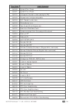
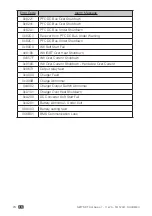
Error Code

Alarm Message

0x6221

PFC DC Bus Over Shutdown

0x6241

PFC DC Bus Over Shutdown

0x62A1

PFC DC Bus Under Shutdown

0x62C0

Recover from PFC DC Bus Under Warning

0x62C1

PFC DC Bus Under Shutdown

0x80C0

INV Soft Start Fail

0x8106

INV IGBT Over Heat Shutdown

0x857F

INV Over Current Shutdown

0x8580

INV Over Current Shutdown - Hardware Over Current

0x8673

Output relay fault

0xA000

Charger Fault

0xA00B

Charge Abnormal

 0xA082

Charger Output Switch Abnormal

0xA101

Charger Over Heat Shutdown

0xA200

DC Converter Soft Start Fail

0xA281

Battery Abnormal - Under Volt

0XA403

Battery setting fault

0X6B01

BMS Communication Loss

Summary of Contents for NETYS NRT3-11000MBP

Page 1: ...7000 11000 VA Hot swap RT version NETYS RT INSTALLATION AND OPERATING MANUAL EN www socomec com netys manuals...

Page 2: ......

Page 3: ...se of installation and operating manual from This Safety Information is to be retained for future reference Reference security information is in English For other languages please contact Socomec or l...

Page 4: ...e warranty The product must be accompanied by proof of purchase such as an invoice or receipt indicating the date of purchase and product ID information model serial numer The sender must also attach...

Page 5: ...ppliances are guaranteed free of material or manufacturing defects under normal conditions of use for a period of 12 months from the date of purchase Socomec will not be responsible for damages includ...

Page 6: ...2 1 General Overview 14 2 2 Exterior Dimensions 14 2 3 Package list 15 3 OPERATION PANEL 17 3 1 LED Indicators 17 3 2 Multi function Buttons 18 3 3 LCD Display 21 4 REAR PANEL 23 5 COMMUNICATION INTER...

Page 7: ...nection Warnings 44 7 2 Input Output Connection 45 7 3 External Battery Pack Connection 48 8 OPERATION 49 8 1 Start up 49 8 2 Turn off 51 8 3 Operating Mode 52 9 LCD DISPLAY SETTINGS 53 9 1 Main Menu...

Page 8: ...to persons or property the products might require compliance with statutory regulations and standards specific local by laws and be adapted accordingly For such uses we would advise you to contact Soc...

Page 9: ...of the mains neutral in any way if the neutral needs to be modifed downstream of the UPS an isolation transformer must be used In the event that the equipment has no automatic backfeed protection con...

Page 10: ...urces Do not open or damage the batteries Do not dispose of batteries in a fire The batteries may explode The released electrolyte is harmful to the skin and eyes and may be toxic A battery can presen...

Page 11: ...e still connected to the UPS even though the UPS is disconnected from the mains Do not forget to cut off the battery source before maintenance When the UPS is connected to external battery packs the i...

Page 12: ...ble surface in a properly ventilated room well away from heat sources and avoiding direct exposure to sunlight Ambient temperature should be maintained between 0 C and 40 C and relative humidity below...

Page 13: ...hat of the UPS so that current peaks can occur during transients loss and restoration of mains supply although these will be of very short duration Where loads generate high leakage current make certa...

Page 14: ...uninterruptible power to your sensitive electronic equipment at all times but also produces greater electronic power efficiency at less cost There are two different ratings 7 kVA and 11 kVA for your...

Page 15: ...issing please contact the dealer immediately Models NRT3 7000MBP NRT3 11000MBP UPS Plug in Manual by Pass Battery Pack 565mm 130mm 220mm 440mm 750mm S S NeTYS RT ESC 4 or 6 4 6 1 1 2 6 1 1 1 2 3 4 5 6...

Page 16: ...Tower Stand Expander 4 PCS 6 PCS 9 Pluggable Terminal 2 PCS 2 PCS 10 Cord End Terminal 6 PCS 6 PCS 11 Terminal for battery wire ground 0 PCS 1 PCS 12 Cable Gland 2 PCS 2 PCS 13 Cable Tie for spare 6...

Page 17: ...ction buttons ESC 100 75 ONLINE Input 232 0V 50 0Hz Output 232 0V 50 0Hz 1 3 1 LED Indicator 3 3 LCD Display 3 2 Multi function Buttons BYPS 231 V PS Figure 3 1 Operation Panel 3 1 LED Indicators No L...

Page 18: ...S will transfer to run in standby or bypass mode The UPS will keep charging the batteries when the UPS is in standby bypass mode To fully turn off the UPS it is advised to disconnect the UPS from the...

Page 19: ...has multiple functions Please refer to the following for detailed information 1 Scrolling Up Increasing Number In the Main Screen press the button for 0 1 seconds and the UPS will directly enter the M...

Page 20: ...display or to decrease a number If the button is pressed for more than 2 seconds the number will be decreased by a single digit every 0 2 seconds automatically until the button is released or the num...

Page 21: ...es the battery capacity level Indicates that the battery is abnormal and needs replacement If the battery is abnormal the battery capacity icon will be empty 4 Indicates the load level 5 When the UPS...

Page 22: ...Mode Diagram Definition No Diagram Description 1 BYPS 231 V PS INV Indicates ONLINE mode 2 BYPS 231 V PS ECO Indicates ECO mode 3 BYPS 231 V PS BATT 999 min Indicates BATTERY mode 4 BYPS 231 V PS Indi...

Page 23: ...485 REPO N L AC INPUT N L UPS OUTPUT TMOV 1 2 3 4 5 6 7 7 9 8 10 11 12 14 16 13 15 Figure 4 1 7 kVA Rear Panel Model NRT3 11000MBP SMART SLOT MANUAL BYPASS SWITCH EXTERNAL BATT CONNECTOR 240V DC 46A...

Page 24: ...to a computer so you can monitor the UPS status 5 RS 232 Port Connects to a computer so you can moni tor the state of the UPS configure the UPS parameters and upgrade the UPS firmware Please refer to...

Page 25: ...s Switch Switches the UPS into manual bypass mode for maintenance without power supply interruption 12 External Batt Connector Connects to the external battery pack optional 7 kVA 192V DC 35A 11 kVA 2...

Page 26: ...ac OS X operating systems Web SNMP manager Web SNMP slot card allowing control via LAN using TCP IP protocol and remote shutdown management BMS JBUS RS232 or RS485 interface allows the UPS to interfac...

Page 27: ...These interfaces are required to run the Local View UPS monitoring and shutdown point to point solution for Windows Linux and Mac OS X operating systems The RS 232 port provides the following function...

Page 28: ...user supplied to connect the UPS with a computer and install the LocalView or Building Managment System BMS software to check and monitor the UPS status This interface is required to run the Local Vie...

Page 29: ...om 1A to 8A 1A default 1 168V 3 12V 16 PCS 11 kVA 274 Vdc from 1A to 6A 2A default 1 210V 3 12V 20 PCS 1 If you need to modify the charge current default setting please contact your local dealer or cu...

Page 30: ...been shut down completely and all isolation switches are OFF switches upstream of the UPS are OFF Set the switch on the back of the battery extension module to the OFF position Connect the battery ext...

Page 31: ...every 2 seconds Overload_125 150 The alarm beeps once every 0 5 seconds 5 Fault The alarm beeps continuously for 5 seconds when the UPS detects an internal fault After the 5 second long beep the alarm...

Page 32: ...the UPS If requested the UPS can also be switched off utilizing a remote external shutdown contact The command is acknowledged when the contact is made and held for 3 seconds default whereas the exter...

Page 33: ...ay and or input contacts Connect Tx to pin 2 Rx to pin 3 and GND C to pin 5 of the computer s RS232 port In Windows start the Hyper Terminal application and proceed to open the specified COM port Set...

Page 34: ...to shut down the UPS or to test the batteries The delay preceding shutdown of the UPS can be set up to 9999 seconds maximum 3 Press 3 to configure NO or NC operation of each relay Configure Input Sign...

Page 35: ...he UPS in a rack by following the procedures below 1 Attach the included bracket ears to the lateral mounting holes of the UPS See Figure 6 1 Figure 6 1 UPS Bracket Ear Installation A2D D2D Inverter O...

Page 36: ...ep 1 Adjust the length of the rail according to the rack Step 2 Tighten the nuts Step 3 Fix the rail on the rack Step 4 Insert the UPS in the rack and tighten the screws 3 If you want to use a non Soc...

Page 37: ...1 according to the size of the UPS see Figure 6 3 Figure 6 4 Tower Stand 4 PCS Tower Stand Expander 4 PCS Tower Stand 4 PCS Tower Stand Expander 6 PCS Figure 6 3 Assemble the Tower Stands for 7 kVA UP...

Page 38: ...ons shown on the panels facing up 4 Place the whole unit inside the tower stands 5 Leave adequate space at least 50cm around all sides of the unit for good ventilation A minimum of two people are requ...

Page 39: ...es below to turn the switch of the Plug in Manual Bypass to the Bypass position to let the UPS automatically shut down Before to proceed to the bypass operation ensure the UPS is set as Standby Mode B...

Page 40: ...manual bypass Disassembly Before disassembling the Plug in Manual Bypass please ensure that you have followed 6 3 1 Precautions Prior to Plug in Manual Bypass Disassembly 1 Remove the four screws fro...

Page 41: ...in manual bypass to the rear of battery pack see Figure 6 12 Figure 6 12 Assemble the Plug in manual bypass 6 3 4 Plug in manual bypass Rack installation If you need to install the Plug in manual byp...

Page 42: ...nt 3 Servicing of batteries and battery packs must be performed or supervised by qualified service personnel who are familiar with batteries battery packs and the required precautions Keep unauthorize...

Page 43: ...nsert a new one Follow the same procedure to replace the battery in the right battery compartment 4 A minimum of two people are required to carry out 3 and 4 1 N L L N UP S OU TP UT AC IN PU T 3 N L L...

Page 44: ...g Suggested Protective Device 7 kVA D curve 40A circuit breaker 11 kVA D curve 63A circuit breaker U P S O U TP U T L2 L1 A C IN P U T L2 L1 Grounded Input Protective Device Grounded Output Protective...

Page 45: ...nput Output Cables Spec Capacity 7 kVA 11 kVA Input Output Cables 6mm2 10mm2 Maximum Tightening Torque For AC Wiring 25 5kgf cm 25 5kgf cm In accordance with National Electrical Codes NEC please insta...

Page 46: ...eed protection device Installation of the backfeed protection device between the AC input and the UPS is highly recommended If there is no backfeed protection device installed between the AC input and...

Page 47: ...ating Voltage Current Suggested Model No 7 kVA 208 220 230 240Vac 40A AF52 30 13 ABB 11 kVA 208 220 230 240Vac 65A AF52 30 13 ABB Backfeed Protection Wiring Diagram Please refer to the diagram below t...

Page 48: ...20A OUTPUT SOCKET 5 10A MAX PER OUTLET P2 P3 P4 P1 RS 232 DRY CONTACT RS 485 REPO OUTPUT BREAKER 1 250V AC 20A WARNING OPENING THIS COVER PLATE WILL CAUSE INVERTER SHUTDOWN ONLY AUTHORIZED SERVICE PE...

Page 49: ...tery amp hour If the UPS connects to an inductive load the inrush current initial surge current may restart the inverter To avoid this situation please turn on the inductive load in bypass mode before...

Page 50: ...e devices see Figure 7 1 installed between the UPS and the loads 8 1 2 Start up with Batteries Cold start 1 Please check the and poles of the batteries and ensure that wiring is correct 2 Turn on the...

Page 51: ...re off 2 1 Press and hold the ON OFF button for 3 seconds 2 release it after you hear one beep 3 use the Scrolling Up or Down button to select Yes and 4 press the Enter button to confirm your selectio...

Page 52: ...y the utility AC power and the batteries are charged The default setting of the UPS is set in BYPASS mode Battery Mode When the UPS is operating during a power outage the batteries provide DC power wh...

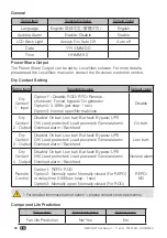
Page 53: ...in this chapter is for reference only Actual display depends on the operation of the UPS The following flow chart helps you to understand how to navigate each display screen 9 1 Main Menu In the Main...

Page 54: ...decrease the parameter value If either of the buttons is pressed for over 2 seconds the LCD will automatically switch between the selectable values every 0 2 seconds until either of the buttons is rel...

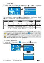
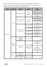
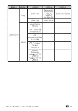
Page 55: ...Mode Parallel On Off Settings Battery General Dry Contact Setting Component Life Prediction Test Battery Aging Reset About Start Battery Test only VRLA Deep Discharge Test only VRLA Local Dry Contact...

Page 56: ...ings such as Output Input Bypass and Battery information 9 1 2 Setting Menu In the Main Menu after selecting Setting press the button to enter the Setting Menu Output Input Bypass Input Battery Measur...

Page 57: ...put Freq Slew Rate 0 5 1 2 Hz sec 1 Hz sec Output Mode Industrial IT IT Standby Mode No output Bypass output No output Overload Alarm 30 105 per step 5 105 1 When the Output Frequency is set as Auto t...

Page 58: ...The setup items ECO Max Voltage and ECO Min Voltage will only be shown on the display when ECO Mode is enabled On Off Settings Setup Item Selectable Value Default Value Energy Saving Option 1 Enable D...

Page 59: ...al Battery Capacity Li battery Rated Voltage Total Capacity Standard battery pack Model Name Quantity Customer own batt pack Voltage Qty Total capaciy 1 2 3 999 Ah one step 1Ah Standard battery pack M...

Page 60: ...en Normal close Disable Dry Contact 2 Output Disable On bat Low bat Bat fault Bypass UPS OK Load protected Load powered General alarm Overload alarm Backfeed On batt Dry Contact 3 Output Disable On ba...

Page 61: ...rger Execute Boost Charge Yes No Alarm Clear Prediction Warning 2 Yes No 1 The item Bypass will be hidden if you set the Standby Mode as Bypass Output To set up Bypass Output please go to Setting Outp...

Page 62: ...t Not Finished Deep Discharge Test Test in Progress Test Result Pass Test Result Fail Test Result Not Finished Local Output Dry Contact Test Dry Contact 1 Dry Contact 1 In Progress Dry Contact 2 Dry C...

Page 63: ...LEVEL 5 Maintenance Log Event List Description Event code YYYY MM DD HH MM SS Error Description Clear Log Yes Cancel About Model Name PR 7K UPS Serial No XXXXXXXXXX UPS Manufacture Date YYYY MM UPS F...

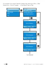
Page 64: ...ass or Fail Start Battery Test Deep Discharge Test Local Dry Contact test Test Battery Aging Reset Log 1 2 Test Battery Test Test In Progress Battery 272 0V Press ESC key to abort test 85 Battery Test...

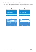
Page 65: ...n the bottom left of the LCD display B Tests Result_ Pass No alarm icon occurs and the UPS runs normally Battery Test Test In Progress Battery 72 0V 85 Battery Test Test In Progress Battery 72 0V 85 B...

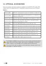
Page 66: ...11000VA NRT OP SNMP NETYS RT WEB SNMP adapter for slot for NETYS RT UPS NRT OP EMD NETYS RT temperature and humiidity environement sensor and 2 inputs NRT OP REL NETYS RT relay board for slot 1x input...

Page 67: ...o the slits and openings that may hinder ventilation Do not allow liquid or any foreign object to enter the battery pack Do not place beverages or any other liquid containing vessels on or near the ba...

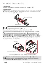
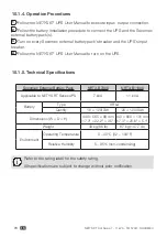
Page 68: ...tery cable 1 to the external battery connector 4 on the UPS and connect the other end to the external battery connector 7 on the Socomec external battery pack Use the provided screws 2 and standoffs 3...

Page 69: ...hat the positive cable connects to the positive pole and the negative cable connects to the negative pole Use the screws 2 and standoffs 3 provided in the battery cable s package to fix the battery ca...

Page 70: ...ow the NETYS RT UPS User Manual to turn on the UPS 10 1 5 Technical Specifications Socomec External Battery Pack NRT3 B7000 NRT3 B11000 Applicable to NETYS RT Series UPS 7 kVA 11 kVA Battery Type VRLA...

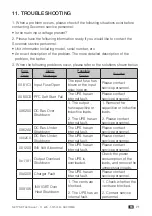
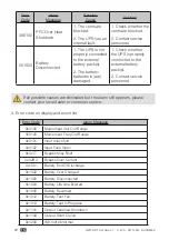
Page 71: ...FC Soft Start Fail The UPS has an internal fault Please contact service personnel 0X6200 DC Bus Over Shutdown 1 The output has capacitive or inductive loads 2 The UPS has an internal fault 1 Remove th...

Page 72: ...ontact service personnel If all possible causes are eliminated but the alarm still appears please contact your local dealer or customer service 4 Error code on display and event list Error Code Alarm...

Page 73: ...N 0x2608 AUTO START UPS 0x3100 Remote INV ON 0x3101 Remote INV OFF 0x3102 Remote Schedule Shutdown Regular form command 0x3103 Remote Schedule Reboot Regular form command 0x3104 Remote ROO On 0x3105 R...

Page 74: ...nder Shutdown 0x80C0 INV Soft Start Fail 0x8106 INV IGBT Over Heat Shutdown 0x857F INV Over Current Shutdown 0x8580 INV Over Current Shutdown Hardware Over Current 0x8673 Output relay fault 0xA000 Cha...

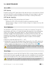
Page 75: ...ncy will quickly shorten the battery life The batteries do not require user maintenance however they should be checked periodically Please follow the suggestions below to ensure a normal battery lifet...

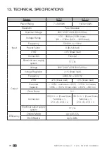
Page 76: ...load iTHD 3 linear load Connection Terminal Electrical input supply system TT TN Output Voltage 200 1 208 1 220 230 240 Vac Voltage Regulation 1 linear load Frequency 50 60 Hz 0 05 Hz vTHD 2 linear lo...

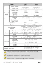
Page 77: ...Port 1 USB Port 1 REPO ROO 1 RS 485 Port 1 Dry Contact 4 OUT 250V 8A resistive load Physical Dimensions W D H 440 665 178 mm 17 3 26 2 7 0 inch 440 750 220 mm 17 3 29 5 8 6 inch Weight 54 kg 119 0 lb...

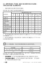
Page 78: ...IX TOXIC AND HAZARDOUS SUBS TANCES AND ELEMENTS Pb Hg Cd Cr 6 PBB PBDE O O O O O O O O O O O O X O O O O O O O O O O O X O O O O O X O O O O O O O O O O O O O O O O O X O O O O O O SJ T11363 2006 X SJ...

Page 79: ......

Page 80: ...e Measurement of electrical parameters Energy management A worldwide presence 80countries where our brand is distributed 12production sites France x3 Italy x2 Tunisia India China x2 USA x3 28subsidiar...

Reviews: