background image

HEAD OFFICE

SOCOMEC GROUP

SAS SOCOMEC capital 10 633 100 €
R.C.S. Strasbourg B 548 500 149 
B.P. 60010 - 1, rue de Westhouse 
F-67235 Benfeld Cedex
Tel. +33 3 88 57 41 41 - Fax -33 3 88 57 78 78
[email protected]

YOUR DISTRIBUTOR / PARTnER

www.socomec.co.uk

Non

 contractual

 document.

 ©

 2018,

 Socomec

 SAS.

 All

 rights

 reserved.

 -

 Document

 printed

 on

 paper

 fr

om

 sustainably

 managed

 for

ests.


Socomec: our innovations supporting your energy performance

The specialist for critical applications

Your power management expert

10 

% of sales revenue  

dedicated to R&D

• 

Energy quality

• 

Energy availability

• 

Energy storage

400

 experts  

dedicated to service provision

• 

 Prevention and repairs

• 

Measurement and analysis

• 

Optimisation

• 

 Consultancy, commissioning 
and training

1

 independent manufacturer

• 

 Control, command of LV 
facilities

• 

Safety of persons and assets

3,200

 employees 

worldwide

• 

 Measurement of electrical 
parameters

• 

Energy management

A worldwide presence

80

 countries 

where our brand is distributed

8

 production sites

• 

France (x3)

• 

Italy

• 

Tunisia

• 

India

• 

China (x2)

27

 subsidiaries

• Australia • Belgium • China • France
• Germany • India • Italy • Netherlands
• Poland • Romania • Singapore 


• Slovenia • Spain • Switzerland • Thailand 
• Tunisia • Turkey • UK • USA

POWER 

sWitCHing

POWER 

mOnitORing

POWER 

COnvERsiOn

ExPERt 

sERviCEs

Summary of Contents for DELPHYS BC

Page 1: ...green power 2 0 and Delphys BC M o d b u s T C P J b u s s e r i a l l i n k Installation and operating manual GB...

Page 2: ...5 5 Com2 Serial link default settings 8 5 6 How to change the serial link 2 settings 8 6 Installation of MODBUS TCP CARD 9 6 1 Com Slots localisation 9 6 2 UPS Com2 Modbus Serial link default settings...

Page 3: ...table in parallel system with centralised bypass 28 10 3 Ups Identification 28 10 4 Date Hours 28 10 5 Ups Configuration 28 10 6 Preliminary Remarks 28 10 7 Ups Status 29 10 8 Ups Alarms 30 10 9 Ups...

Page 4: ...Whatever the repairs they must be made only by authorised staffs which have been suitably trained For an optimal operation it is recommended to maintain the ambient temperature and humidity of the DEL...

Page 5: ...ng Input Registers 16 bits function 6 for writing single Registers to control DELPHYS Green Power The data field is composed of 1 word defined by a MSB most significant byte and a LSB lowest significa...

Page 6: ...and fixed with 2 crews 5 3 Modbus interface in parallel system configuration There is only one MODBUS serial link interface for a parallel system configuration One serial interface is used for the who...

Page 7: ...esistors could be removed easily if needed 5 4 3 Isolated RS422 connection 4 wires connection dip switch 1 and 2 allows connecting the terminal resistor Insulation via opto coupler 4 polarization resi...

Page 8: ...be set from the control panel 5 6 How to change the serial link 2 settings Available baud rate 1200 2400 4800 9600 19200 bauds Parity EVEN ODD NONE Slave number 1 to 32 Please see on the manual of the...

Page 9: ...rrect localisation of the com slot 2 6 2 UPS Com2 Modbus Serial link default settings Baud rate 9600 bauds Parity NONE Data 8 bits Stop 1 bit Slave 1 The serial link settings can be set from the contr...

Page 10: ...Unzip the file on your computer only Windows run AGILIPLUG Finder program SEARCHING UPS CONNECTED AGILIPLUG Finder lists all IP addresses of MODBUS TCP interface connected to network INTERFACE CONFIG...

Page 11: ...f the MODBUS table 6 4 Frame errors management In case of wrong data request the DELPHYS Green Power answers with the following frame error Error function code Error code Cause 80 code function 1 Func...

Page 12: ...s should be read completely this means the number of word to read is equal to the table length The measurements table should be read word by word or per group without exceed the length of the table fr...

Page 13: ...D02 Month day of week 1 WORDS 0x1362 Byte value MSB month LSB day of the week 1 Monday 7 Sunday D03 Year 1 WORDS 0x1363 00 2000 8 5 Ups Configuration Address 0x1120 16 Words Code Measurements Unit Add...

Page 14: ...ntactor closed 12 S061 Bypass switch activated 13 S062 14 S063 Servicing alert 15 S064 Rectifier input supply fault 0 0x1144 S065 Bypass input supply out of tolerance 1 S066 Bypass input supply failur...

Page 15: ...rallel if present S095 Q22 switch closed 15 Only on parallel if present S096 Auxiliary input 1 active 0 0x1146 S097 Auxiliary input 2 active 1 S098 Auxiliary input 3 active 2 S099 Auxiliary input 4 ac...

Page 16: ...ACS synchro source fault 13 A046 14 A047 15 A048 Operating on battery 0 0x114B A049 Battery alarm 1 A050 Battery room 2 A051 Battery discharged 3 A052 End of autonomy time 4 A053 Battery test failure...

Page 17: ...89 9 A090 10 A091 11 A092 12 A093 13 A094 Output since xx minutes on auto bypass 14 A095 Unit General alarm 15 A096 Fly Wheel disconnected 0 0x114E If set A097 Fly Wheel Critical 1 A098 Fly Wheel prev...

Page 18: ...0 M049 Output Apparent Power L2 kVA 1 M050 Output Apparent Power L3 kVA 2 M051 Output Crest Factor 3 M052 Output load rate L1 4 M053 Output load rate L2 5 M054 Output load rate L3 6 M055 Unit load rat...

Page 19: ...V3 V D M078 Bypass input supply frequency x10 Hz E M079 Ambient T C F M080 Vdc V 0x1250 M081 M082 Battery voltage string V 2 M083 M084 Battery current A 4 M085 M086 6 M087 7 M088 8 M089 9 M090 A M091...

Page 20: ...rface in remote mode using ADICOM interface The control table below shows if the selected control is allowed or not If the control sent to the UPS is not allowed the function will be ignored Controls...

Page 21: ...in the UPS unit 1 com slots 2 in case of modular system see bellow MODBUS link setting The setting of the link is made from the mimic panel unit where the board is plugged How to read data In the MOD...

Page 22: ...ements 0xm220 80 3 READ Controls permission 0xm150 4 3 READ UPS Controls 0xm190 4 6 WRITE m number of unit Example 0x3100 ID of unit 3 0x3140 UPS States 0x3143 unit 3 states 9 3 Ups Identification Add...

Page 23: ...13 UPS Rectifier input supply absence 13 S014 14 S015 Remote control enabled 15 S016 Unit 1 operating 0 0x0141 S017 Unit 2 operating 1 S018 Unit 3 operating 2 S019 Unit 4 operating 3 S020 Unit 5 opera...

Page 24: ...9 synthesis of all unit alarms A010 UPS on battery 10 A011 UPS Battery discharge 11 A012 UPS End of autonomy 12 A013 UPS Temperature alarm 13 A014 14 A015 15 A016 Unit 1 general 0 0x0149 A017 Unit 2...

Page 25: ...ut Power factor L1 A M011 Output Power factor L2 B M012 Output Power factor L3 C M013 Output Active Power L1 kW D M014 Output Active Power L2 kW E M015 Output Active Power L3 kW F M016 Output Apparent...

Page 26: ...trol it is necessary to set the serial interface in remote mode using the Human Machine Interface Local controls are then locked The control table below shows if the selected control is allowed or not...

Page 27: ...e is plugged in the com slots 2 of bypass cabinet MODBUS link setting The setting of the link is made from the mimic panel unit where the board is plugged How to read data In the MODBUS table one part...

Page 28: ...00 32 3 READ UNIT Measurements 0xm220 80 3 READ Controls permission 0xm150 4 3 READ UPS Controls 0xm190 4 6 WRITE m 1 number of module m 8 m 15 Bypass data Example 0x3100 ID of unit 3 0x3140 UPS State...

Page 29: ...ence 13 S014 14 S015 Remote control enabled 15 S016 Module 1 operating 0 0x0141 S017 Module 2 operating 1 S018 Module 3 operating 2 S019 Module 4 operating 3 S020 Module 5 operating 4 S021 Module 6 op...

Page 30: ...of all unit alarms A010 UPS on battery 10 A011 UPS Battery discharge 11 A012 UPS End of autonomy 12 A013 UPS Temperature alarm 13 A014 14 A015 15 A016 Module 1 general 0 0x0149 A017 Module 2 general...

Page 31: ...tput Power factor L1 A M011 Output Power factor L2 B M012 Output Power factor L3 C M013 Output Active Power L1 kW D M014 Output Active Power L2 kW E M015 Output Active Power L3 kW F M016 Output Appare...

Page 32: ...control it is necessary to set the serial interface in remote mode using the Human Machine Interface Local controls are then locked The control table below shows if the selected control is allowed or...

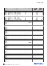
Page 33: ...3 S052 4 S053 5 S054 Output switch 3 closed 6 S055 7 S056 8 S057 9 S058 10 S059 1 S060 12 S061 Bypass switch activated 13 S062 14 S063 Servicing alert 15 S064 0 0xF144 S065 1 S066 2 S067 3 S068 4 S06...

Page 34: ...input 1 active 0 0xF146 S097 Auxiliary input 2 active 1 S098 Auxiliary input 3 active 2 S099 Auxiliary input 4 active 3 S100 Auxiliary input 5 active 4 S101 Auxiliary input 6 active 5 S102 Auxiliary...

Page 35: ...A038 6 A039 7 A040 8 A041 Bypass critical 9 A042 Common critical 10 A043 FAN alarm 11 A044 Back feed protection open 12 A045 ACS synchro source fault 13 A046 14 A047 15 A048 0 0xF14B A049 1 A050 2 A0...

Page 36: ...083 3 A084 4 A085 5 A086 6 A087 7 A088 8 A089 9 A090 10 A091 11 A092 12 A093 13 A094 Output since xx minutes on auto bypass 14 A095 Bypass General alarm 15 A096 0 0xF14E A097 1 A098 2 A099 3 A100 4 A1...

Page 37: ...M043 Output Power factor L2 B M044 Output Power factor L3 C M045 Output Active Power L1 kW D M046 Output Active Power L2 kW E M047 Output Active Power L3 kW F M048 Output Apparent Power L1 kVA 0xF230...

Page 38: ...6 Bypass input supply voltage V2 V C M077 Bypass input supply voltage V3 V D M078 Bypass input supply frequency x10 Hz E M079 Ambient T C F M080 0xF250 M081 1 M082 2 M083 3 M084 4 M085 M086 6 M087 7 M...

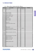
Page 39: ...S060 Inverter switch contactor closed 12 S061 13 S062 14 S063 Servicing alert 15 S064 Rectifier input supply fault 0 0xm144 S065 Bypass input supply out of tolerance 1 S066 2 S067 Bypass input supply...

Page 40: ...uxiliary input 1 active 0 0xm146 S097 Auxiliary input 2 active 1 S098 Auxiliary input 3 active 2 S099 Auxiliary input 4 active 3 S100 Auxiliary input 5 active 4 S101 Auxiliary input 6 active 5 S102 Au...

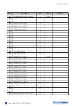
Page 41: ...rating on battery 0 0xm14B A049 Battery alarm 1 A050 Battery room 2 A051 Battery discharged 3 A052 End of autonomy time 4 A053 Battery test failure 5 A054 Earth leakage fault 6 A055 Battery circuit op...

Page 42: ...9 9 A090 10 A091 11 A092 12 A093 13 A094 14 A095 Unit General alarm 15 A096 Fly Wheel disconnected 0 0xm14E If set A097 Fly Wheel Critical 1 A098 Fly Wheel preventive 2 A099 3 A100 4 A101 Aux input al...

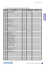
Page 43: ...0xm230 M049 Output Apparent Power L2 kVA 1 M050 Output Apparent Power L3 kVA 2 M051 Output Crest Factor 3 M052 Output load rate L1 4 M053 Output load rate L2 5 M054 Output load rate L3 6 M055 Unit loa...

Page 44: ...Battery voltage string V 2 M083 M084 Battery current A 4 M085 M086 6 M087 7 M088 8 M089 9 M090 A M091 Battery T C B M092 Average battery T C C M093 Battery capacity Ah D M094 Battery capacity E M095 R...

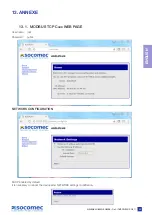
Page 45: ...TCP Card WEB PAGE User name root Password public NETWORK CONFIGURATION DHCP enabled by default It is necessary to reboot the device after NETWORK settings modification 45 DELPHYS GREEN POWER Ref IOMDG...

Page 46: ...the number of bytes length of the message Note The CRC is suppressed in the encapsulated MODBUS frame REPLY OF THE UPS IN MODE JBUS MODBUS RTU Original frame 01 03 06 0002 0184 0000 1960 Encapsulated...

Page 47: ......

Page 48: ...cated to R D Energy quality Energy availability Energy storage 400experts dedicated to service provision Prevention and repairs Measurement and analysis Optimisation Consultancy commissioning and trai...

Reviews: