Page 3 - 14
TL49J
coil is activated, a strong magnetic force is felt pulling the screwdriver towards the nut securing the
coil to the cartridge.
Do not use great force when securing the coil to the cartridge as the casing can easily crack due to
thermal expansion when heated up during use. The coil will fail if water gets through the crack.
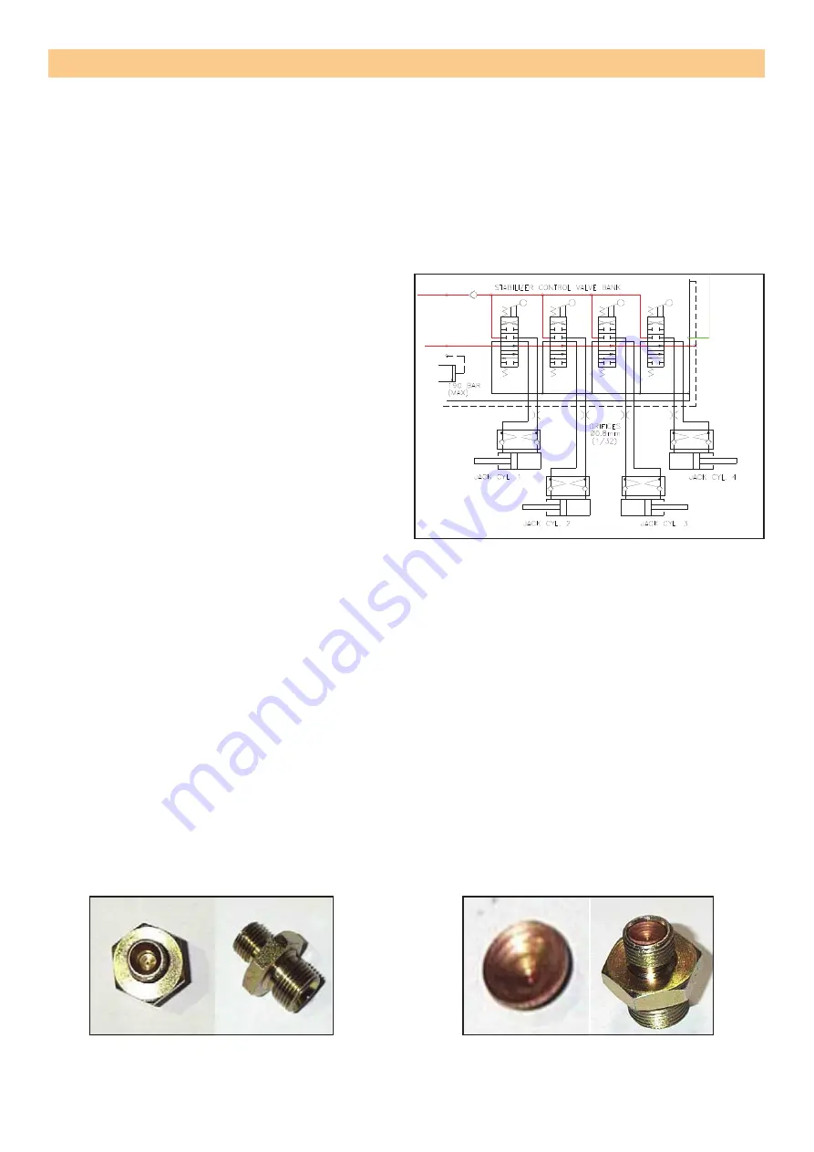
OUTRIGGER CONTROL VALVE
This valve is not interchangeable with the ground control valve even tough it is a 4 bank valve block
with a relief valve and looks identical to the ground controls.
When the spool is in the neutral position, the
annular side of the ram is attached to the tank
line. This is done to ensure that the pilot pressure
holding the check valve on the full bore open is
drained of quickly to tank so that the check valve
closes quickly.
If the valve block is replaced, make sure that
the piping is done exactly as shown. Rely on the
closed port as back up for the check on the full
bore side.
Note that earlier versions might not have this type
of spool. This type can easily be identified as it
has a “DIN - Oil” stamped on the end cap. This
type used a standard closed centre valve block.
The leakage rate across the closed centre spool
is high enough to ensure that the deck would
close.
Each A port has a restrictive hose adaptor fitted in the valve block. If the restrictor gets blocked, the
cylinder will not operate correctly.
When looking for a fault relating to cylinders and valve blocks, swapping hose connections can eas
-
ily provide a good pointer to where the fault is. If the fault position doesn’t change, then the fault is
in the valve block. If the fault position moves, then the fault is in the cylinder.
Do not overtighten the hose fittings. Overtightening can lead to leakages due to deformation of the
adaptor cone.
RESTRICTORS
All valve blocks have restrictors fitted at different locations. The current versions (2002) of the TL37J
uses a hose adapter with a drilled hole. Other types which have been in use (and currently are on
other machines) are a simple copper washer with a sized hole. The copper washer is squashed
between the hose fitting and the adapter screwed into the valve block.
It is easy to observe that a copper washer type restrictor has been used as it looks like the hose
fitting is not screwed fully down onto the adapter in comparism to the hose fitting next to it. A large
force is needed when tightening the hose fitting to prevent leaks.
SERVICE AND REPAIR
Figure 3-12
: Schematic view of outrigger
control valve.
Figure 3-13
: Hose adaptor shown here with
drilled hole. If cylinder movement is erratic,
check for contamination.
Figure 3-14
: Copper restrictor fitted
loose in the hose adaptor. Hose end
requires more torque to prevent oil
leak when securing hose.
Summary of Contents for TL37-01-007625
Page 1: ...TL37J PARTS MANUAL TL37J PARTS MANUAL...
Page 8: ......
Page 16: ...REPAIR PARTS TL37J PARTS MANUAL JOCKEY WHEEL JOCKEY WHEEL Tue Mar 23 07 46 30 UTC 2021 2 3...
Page 18: ...REPAIR PARTS TL37J PARTS MANUAL AXLE ASSEMBLY AXLE ASSEMBLY Tue Mar 23 07 46 30 UTC 2021 2 4...
Page 20: ...REPAIR PARTS TL37J PARTS MANUAL BRAKE ASSEMBLY BRAKE ASSEMBLY Tue Mar 23 07 46 31 UTC 2021 2 5...
Page 28: ...REPAIR PARTS TL37J PARTS MANUAL SLEW ASSEMBLY SLEW ASSEMBLY Tue Mar 23 07 46 33 UTC 2021 2 9...
Page 33: ...REPAIR PARTS TL37J PARTS MANUAL CAGE ASSEMBLY CAGE ASSEMBLY Tue Mar 23 07 46 34 UTC 2021 2 11...
Page 35: ...REPAIR PARTS TL37J PARTS MANUAL BOTTOM RAM BOTTOM RAM Tue Mar 23 07 46 34 UTC 2021 2 12...
Page 37: ...REPAIR PARTS TL37J PARTS MANUAL TOP RAM TOP RAM Tue Mar 23 07 46 34 UTC 2021 2 13...
Page 43: ...REPAIR PARTS TL37J PARTS MANUAL OUTRIGGER RAM OUTRIGGER RAM Tue Mar 23 07 46 35 UTC 2021 2 16...
Page 55: ...REPAIR PARTS TL37J PARTS MANUAL DECALS UK KIT DECALS UK KIT Tue Mar 23 07 46 38 UTC 2021 2 22...
Page 102: ......
Page 135: ...Page 3 30 TL37J...
Page 136: ...Page 4 1 TL37J TROUBLESHOOTING CONTENTS FAULT FINDING 4 2 FAULT FINDING MATRIX 4 4...
Page 146: ...BATTERY CIRCUIT SCHEMATIC...
Page 147: ...BATTERY HYDRAULIC FLOW DIAGRAM 29 BATTERY HYDRAULIC FLOW DIAGRAM...
Page 148: ...MAINS CIRCUIT SCHEMATIC...
Page 149: ...MAINS HYDRAULIC FLOW DIAGRAM 31 MAINS HYDRAULIC FLOW DIAGRAM...
Page 150: ...PETROL CIRCUIT SCHEMATIC...
Page 151: ...PETROL HYDRAULIC FLOW DIAGRAM PETROL HYDRAULIC FLOW DIAGRAM...
Page 152: ...BI FUEL PETROL CIRCUIT SCHEMATIC...
Page 153: ...BI FUEL HYDRAULIC FLOW DIAGRAM BI FUEL HYDRULIC FLOW DIAGRAM...
Page 154: ...BI FUEL DIESEL CIRCUIT SCHEMATIC...
Page 155: ...DIESEL CIRCUIT SCHEMATIC...
Page 156: ...MAINS GEN SET CIRCUIT SCHEMATIC...
Page 157: ...BATTERY ANSI CANTILT CIRCUIT SCHEMATIC From SN TL37J 01 00291...
Page 158: ...MAINS ANSI CANTILT CIRCUIT SCHEMATIC From SN TL37J 01 00291...
Page 159: ...PETROL ANSI CANTILT CIRCUIT SCHEMATIC From SN TL37J 01 00291...
Page 160: ...BI FUEL PETROL ANSI CANTILT CIRCUIT SCHEMATIC From SN TL37J 01 00291...
Page 161: ...BI FUEL DIESEL ANSI CANTILT CIRCUIT SCHEMATIC From SN TL37J 01 00291...
Page 162: ...DIESEL ANSI CANTILT CIRCUIT SCHEMATIC From SN TL37J 01 00291...
Page 163: ...MAINS GEN SET ANSI CANTILT CIRCUIT SCHEMATIC From SN TL37J 01 00291...


