37
Cut Guide Placement
Prior to preparation of the locking features for cut
guides on to the patient bone surface using the
NAVIO™ handpiece in speed control, the user is
presented with a cut guide placement screen,
where the goal is to size the appropriate cut guide
for the operation.
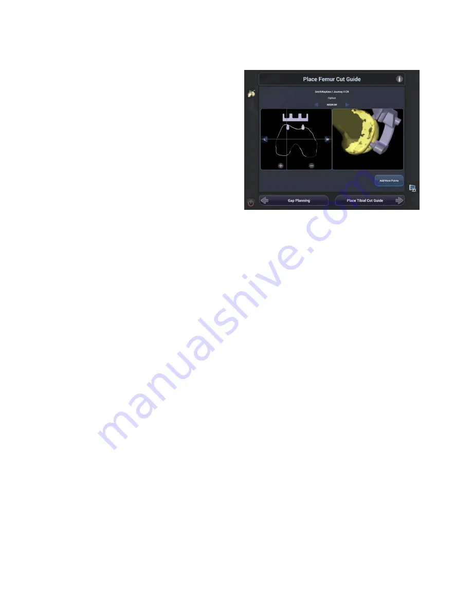
Femur Cut Guide Placement
The purpose of this stage is to ensure that all four
locking features on the femur distal cut guide
assembly (consisting of the distal cut guide and
stabilizer block) have purchase into the bone
surface. The cross section view on the left depicts
a transverse cross section, where the user can
visualize the bone in yellow, and the cut block in
grey.
The first step is to select an appropriate cut guide
option by selecting from Small, Medium, or Large
on the top of the screen. After an appropriate size
of the cut guide is selected, slicing through the
transverse cross section view, ensure that the
anterior locking features of the cut guide have
purchase into the bone surface and are centralized
close to the anterior crests of the femur bone
surface. Confirm that the distal lock features
are also embedded into the bone surface, by
referencing the cross section view, as well as the
3D view. (Figure 57)
Tibia Cut Guide Placement
In this stage, ensure that all four locking features
on the tibia cut guide assembly have purchase into
the bone surface. The cross section view on the
left, depicts a transverse cross section, where the
user can visualize the bone in yellow, and the cut
block in grey.
First, choose an appropriate cut guide option by
selecting from Small, Medium, or Large on the top
of the screen. After an appropriate size of the cut
guide is selected, slice through the transverse
cross section view and ensure that the locking
features of the cut guide have sufficient purchase
into the bone surface. Pay close attention to the
angled posterior locking features, ensuring that
they are both buried deep into the bone surface.
It may be helpful to position the cut guide further
away from the medial (or more severely diseased)
condyle such that the medial posterior locking
feature is buried into the intercondylar eminence to
achieve sufficient purchase into the bone.
Figure 57.
Visualize the cut guide placement on the cross section and
solid surface models. Ensure that there is engagement of the locking
features on to the bone surface.
8
Bone Cutting


