30
Button Mapping
Femur
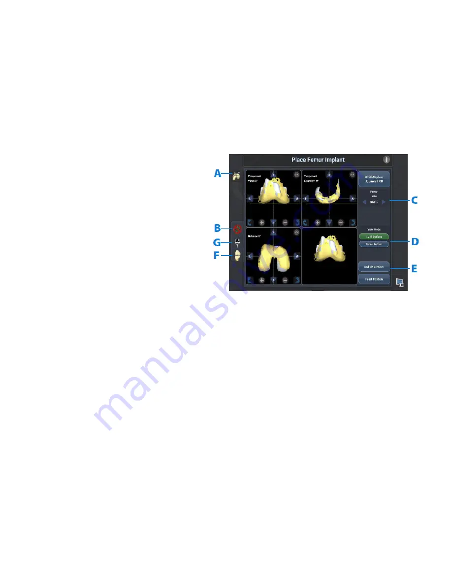
While the NAVIO™ System for Total Knee
Arthroplasty User’s Manual details each button on
this screen, the following five buttons (Figure 46)
are particularly critical to understand.
A
- The Checkpoint Verification button is used to
manually force a check of the checkpoints in the
femur and tibia. The user should utilize this button
if they think either of the tracker arrays shifted
during registration or planning.
B
- Press the Green Dots button to show and hide
the cloud of discreet green points. It is generally
helpful to hide the green points in order to view the
meshed virtual
surface unobstructed.
C
- Femur implant size changing arrows will size
up (right) or size down (left) and display between
the arrows the selected size. This size will map
to the manufacturer’s provided labeling on the
component boxes.
D
- Solid Surface and Cross Section buttons allow
the user to toggle between a 2D and 3D view of
the virtual implant with respect to the digitized
surface.
E
- Add Femur Points is a useful tool to select to
bring the user directly backwards through the
workflow to the femur free-point collection stage,
where additional points may
be mapped.
F
- The virtual bone cut button is used to toggle
through the interpolated bone model for virtual
cut view, collected surface mesh view, and hiding
the view of the bone altogether, based on the
component plan.
G
- Selecting this button toggles an implant on and
off on the planning view screens.
Figure 46.
6
Implant Planning


