12
Figure 8.
Placing Tracking Hardware
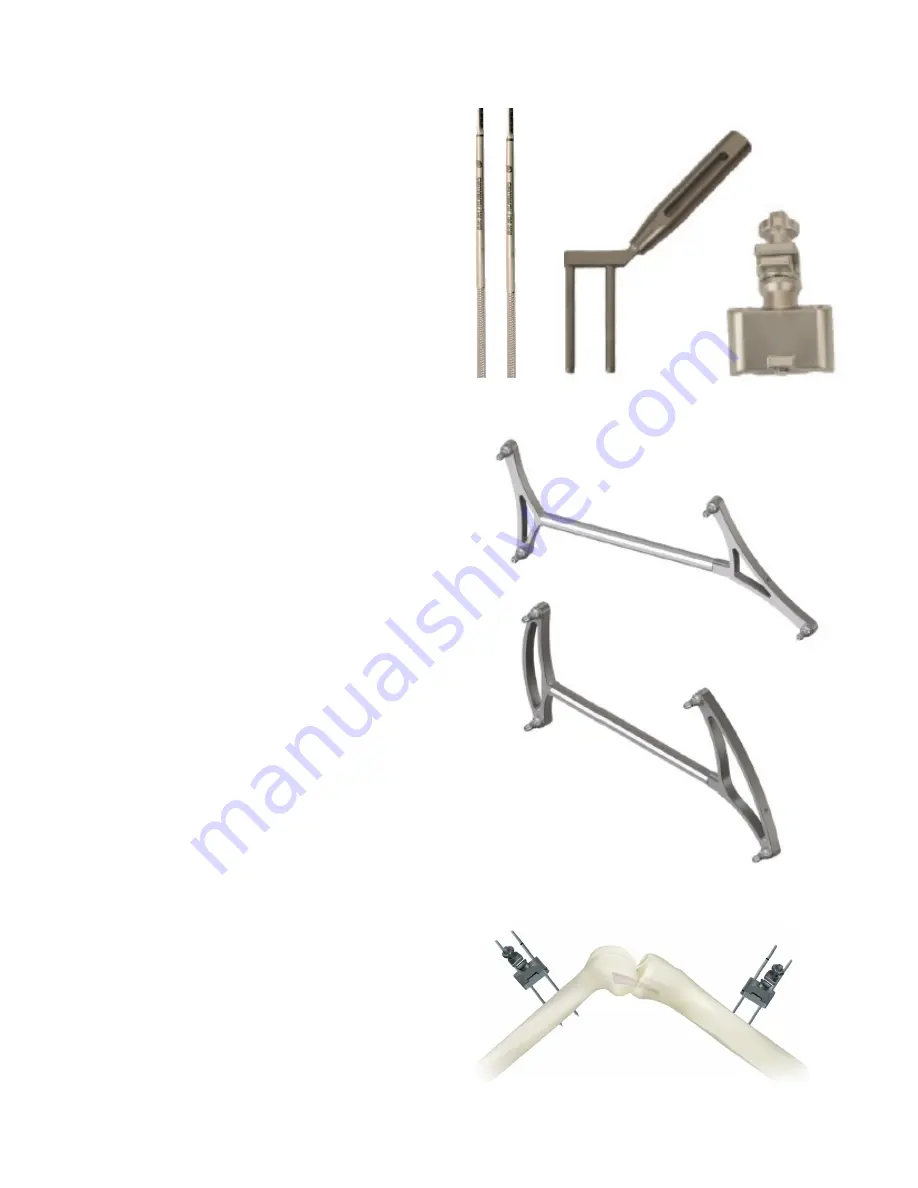
Rigid fixation of the femur and tibia tracking frames
to the bone is critical for a successful NAVIO™-
assisted surgery. The NAVIO system utilizes a two-
pin bi-cortical fixation system. This fixation system
is installed using bone screws, a tissue protector,
and tracker clamps (2x) (Figure 7). Once fixed to the
bone, the tracking frames (Figure 8) are oriented
towards the optical tracking camera so the markers
are in view. With the operative leg in 90 degrees of
flexion, utilize the following procedure:
Tibia Tracker Array Placement
•
Percutaneously place the first bone screw one
hand’s breadth (four fingers) inferior to the tibial
tubercle on the medial side of the tibial crest (Figure
9.)
•
Drill the bone screw into the tibia slowly,
perpendicular to the bony surface, taking care to
engage the opposing cortex and stop.
•
Use the tissue protector to mark the position of the
second bone screw inferior to the initial placement.
Engage the second screw with the bone through
the tissue protector to ensure the pins are placed
parallel to each other.
•
Slide the bone clamp (with the clamp hardware
oriented towards the optical tracking camera) over
the two bone screws until the bottom of the clamp
is within 1 cm of the patient’s skin, taking care not
to place the clamp touching the skin.
•
Clamp the tibia array into the bone clamp along
the length of the bar on the array. Place the smaller
side of the arrays closest to the operative site
(Figure 9). Orient the spheres towards the camera
and slide the array away from the incision site.
Femur Tracker Array Placement
•
Percutaneously place the first bone screw one
hand’s breadth (five fingers) superior to the patella
in the center of the femur (Figure 9).
•
Drill the bone screw into the femur slowly, taking
care to engage the opposing cortex and stop.
•
Utilize the tissue protector to mark the position of
the second bone screw. Engage the screw with the
bone through the tissue protector to ensure the
pins are placed parallel to each other.
Figure 7.
Figure 9.
2
Bone Tracking Hardware
Femur Tracker Frame
Tibia Tracker Frame


