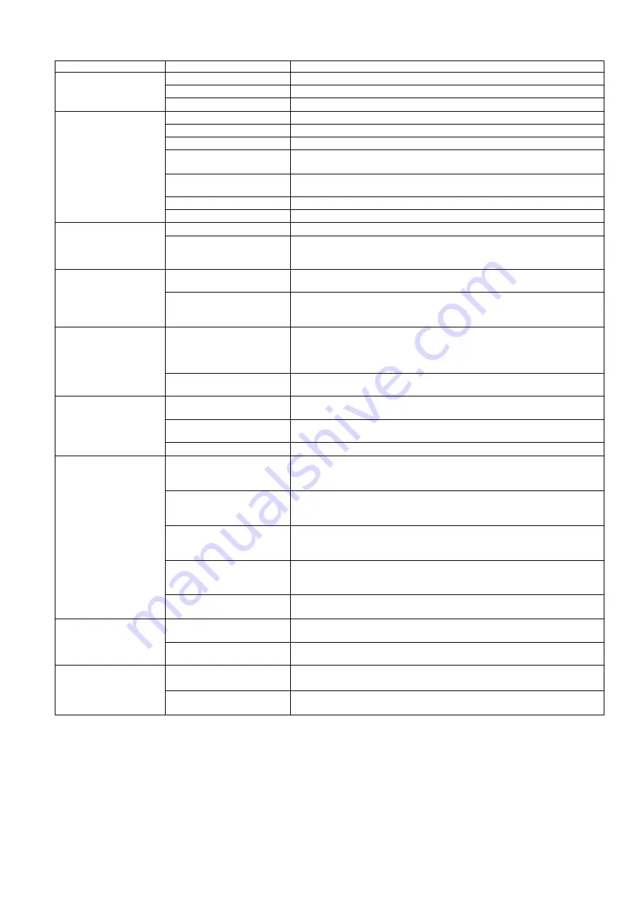
background image

- 21 - 

9. Troubleshooting


Detail of trouble 

Cause 

Countermeasure 

Operation is not 
smooth 

1. Lubrication failure 

Clean components and apply specified grease to them. 

2. Piston rod deformation 

Replace cylinder and adjust load and position. 

3. Insufficient air pressure 

Supply an appropriate amount of pressure. 

Output is decreasing 

1. Piston seal air leakage 

Replace piston seal. 

2. Rod seal air leakage 

Replace cylinder 

3. Air pressure decrease 

Review the amount of pressure and capacity of the pressure source. 

4. Insufficient air flow 

Maintain and/or clean air passages. Air flow might have decreased 

  due to deformation and/or foreign matter. 

5. Incorrect cylinder 

mounting position 

Mount cylinder correctly to avoid excessive strain. 

6. Piston rod deformation 

Replace cylinder and adjust load and position. 

7. Lubrication failure 

Refer to “Operation is not smooth” above. 

Piston operates too 
fast 

1. No speed controller 

Use a speed controller appropriate to the cylinder size. 

2. Precise adjustment of   

speed controller is   
insufficient 

Select an appropriate speed controller to secure required operating 

  speed referring to speed controller flow rate characteristic curves. 

Piston operates too 
slowly 

1. Directional control valve 

  is too small 

Use a larger size of valve. 

2. Large resistance of   

equipment in the system 

Use valves and other equipment of appropriate sizes. Do not forget 
to check piping and fitting sizes. Use appropriate piping and 
equipment on the outlet side. 

Cylinder occasionally 
stops operating 

1. Very low speed 
    operation 

Operate cylinder within the specified range of speed. Very low speed 

  operation reduces the pressure difference between inlet side and 
  outlet side of the cylinder to almost zero, which may lower sealing 
  ability and result in malfunction. 

2. Defective equipment   

other than cylinder 

Examine all the equipment used in the system one by one. 

Cylinder stops 
operating 

1.


Piston seal damaged 

Replace piston seal if air comes out from exhaust port of valve 

  continuously. 

2. Defective equipment 
    other than cylinder 

Examine all the equipment used in the system one by one. 

3.


Insufficient air pressure 

Supply an adequate amount of pressure. 

Piton rod deformed or 
broken 

1. High speed operation 

Replace cylinder. Operate it within the specified range of speed. High 

  speed operation may result in cylinder deformation or breakage due 
  to impact force. 

2.


Abnormal external force 

  applied 

Replace cylinder after removing mechanical interference, unbalanced 

  load or excessive load which may cause cylinder deformation or 
  breakage. 

3. Impact of pallet while 

the lever is standing 
erect 

For a lever with built-in shock absorber type, do not allow the next 

  pallet to collide while the lever is standing erect. Otherwise, all   

energy will be applied to the cylinder body. 

4. External force applied 

from the opposite side 
when the lever is locked 

For cylinders with locking mechanism, do not apply an external 

  force from the opposite side when the lever is locked. 

5. Shock absorber 

adjustment problem 

Adjust the shock absorber to the optimum absorption position to stop 

  work pieces gently. 

Cylinder speed cannot 
be controlled with   
speed controller 

1.


Unsuitable speed 

controller 

Select an appropriate speed controller for the desired operating   
speed. 

2. Defective speed   

controller 

Replace speed controller. 

Cylinder stick-slip 
operation 
 

1. High load factor 


Increase operating pressure. 

Use cylinder with larger bore. 

2. Meter-out circuit not 

  used 

Control operating speed with a meter-out circuit. Meter-in circuit   
may make operation unstable at low pressure and speed. 


Summary of Contents for RS2H Series

Page 1: ...Doc no RS2H OM0012P B PRODUCT NAME HEAVY DUTY STOPPER CYLINDER MODEL Series Product Number RS2H Series 50 to 80...

Page 2: ...rber resistance adjustment method 4 Operation P 12 5 Pneumatic circuit P 12 6 Maintenance P 13 6 1 Check items 6 2 How to replace shock absorber 6 3 Seal replacement 6 3 1 Disassembly Reassembly 6 3 2...

Page 3: ...ment failure when configuring the equipment 2 Only personnel with appropriate training should operate machinery and equipment The product specified here may become unsafe if handled incorrectly The as...

Page 4: ...replacement product or necessary parts will be provided This limited warranty applies only to our product independently and not to any other damage incurred due to the failure of the product 3 Prior...

Page 5: ...e Standard stroke 50 30 63 30 80 40 1 4 Cylinder mass Action Bore size mm Mass kg Double acting Single acting spring retraction Double acting with spring 50 1 70 63 2 78 80 4 96 Bore size mm 50 63 80...

Page 6: ...lateral load F at operating pressure P For relationship between lateral load F and operating pressure P refer to Figure 2 1 P7 FA F YES Determine final model Figure 1 Impact of transferred object Mod...

Page 7: ...Operating range Lower limit Lower limit Upper limit Upper limit Mass of transferred object m kg Mass of transferred object m kg Transfer speed v m min Transfer speed v m min Coefficient of friction 0...

Page 8: ...ll parts remain secure 6 Consider a possible loss of power source Measures should be taken to protect against human injury and equipment damage in the event that there is a loss of power to equipment...

Page 9: ...bowl will overflow and allow the condensation to enter the compressed air lines This may cause malfunction of pneumatic equipment If the drain bowl is difficult to check and remove installation of a...

Page 10: ...and or shock 4 Do not mount the product in locations where it is exposed to radiant heat 5 Do not use in dusty locations or where water or oil etc splash on the equipment 3 4 Cautions for mounting Wa...

Page 11: ...e very careful when handling the product Depending on the handling method there is a risk that the corners of the product will injure your hand or fingers etc 3 5 How to change the relationship betwee...

Page 12: ...o secure the shock absorber dial Set screw M4 tightening torque 1 5N m Figure 6 Warning 1 Do not put your hand or finger between the lever holder and rod cover Do not put your hand or finger between t...

Page 13: ...k the condition of this and apply grease as necessary 4 Do not let your hand become caught when operating the cylinder The lever holder goes up and down while the cylinder is in operation Take care no...

Page 14: ...drive speed gradually increasing from a low speed to the desired speed setting 6 Maintenance 6 1 Check items The following checks are required for proper cylinder operation 1 Smoothness of performanc...

Page 15: ...firming that appropriate measures are in place to prevent sudden movement of cylinders 6 2 How to replace shock absorber Loosen the shock absorber set screw M4 on the stopper incline the lever by 90 a...

Page 16: ...exagon socket head cap screws with a hexagon wrench Detach the rod cover and piston rod from the cylinder tube When reassembling apply thread locker to the hexagon socket head cap screws and tighten H...

Page 17: ...y to prevent the gasket from coming off 3 O Ring Apply grease thinly to prevent the gasket from coming off 4 Cylinder components Apply grease to each part of the cylinder Figure 14 Figure 14 6 3 4 Sea...

Page 18: ...n a box Avoid direct sunlight and store seals at a low temperature and humidity Take special care to isolate and shield them from equipment which generates heat radiation and ozone Do not pile up a la...

Page 19: ...9 0 23 5 11 0 23 5 7 0 19 5 10 5 13 0 63 25 5 12 5 25 5 14 5 25 5 10 5 21 5 14 0 16 5 80 39 5 19 5 39 5 21 5 39 5 17 5 35 5 21 0 23 5 The values in brackets are for D A96 Auto switch Auto switch Auto...

Page 20: ...socket head cap screw M2 5X9 5L 1 to 2 turns Insert the temporarily tightened mounting bracket into the mating groove of the cylinder tube and slide the auto switch onto the cylinder tube through the...

Page 21: ...ard IP67 Immersion proof shape and oil proof shape by JEM standard IP67G Note 1 At load current 100 mA and cord length of 2 m Note 2 Between case and whole charging part 8 2 How to mount proximity swi...

Page 22: ...cylinder to almost zero which may lower sealing ability and result in malfunction 2 Defective equipment other than cylinder Examine all the equipment used in the system one by one Cylinder stops opera...

Page 23: ...ce cylinder away from it or shield it If cylinder is getting hot modify operating conditions such as frequency to keep the temperature below 60 C Replace cylinder if switch still does not turn on with...

Page 24: ...23...

Page 25: ...ion P 17 23 Wrapping of sealant tape is changed P 9 4 14 1 Sotokanda Chiyoda ku Tokyo 101 0021 JAPAN Tel 81 3 5207 8249 Fax 81 3 5298 5362 URL http www smcworld com Note Specifications are subject to...

Reviews: