background image

-22- 


No.EX##-OMV0017-D


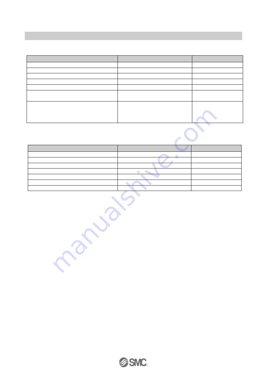
Remote unit setting items (example using compact wireless unit EXW1-RDXNE4## / EXW1-RDYNE4## / 

EXW1-RDM#E3##) 

Parameter name 

Set value 

Initial value 

Input size*


16 points (16 bits)


16 points (16 bits)


Output size (includes valves)*


16 points (16 bits)


16 points (16 bits)


Wireless signal


Active / Idle


Active


Power Supply Voltage Monitor (Control/Input)


Enable / Disable


Enable


Power Supply Voltage Monitor (Output)


Enable / Disable


Disable


Output action when upper communication is 
disconnected.


Clear / Hold


Clear


Output action when wireless communication is 
disconnected.


Clear / Hold


EXW1-RDYNE4#: 

Clear 

EXW1-RDM#E3#: 

Hold


* Although the number of occupied inputs / outputs of the EXW1-RDM# is fixed at 16 (16 bits), only the lower 8 bits are 

available. 


Remote unit setting items (example using manifold-type wireless unit EX600-WSV#) 

Parameter name 

Set value 

Initial value 

HOLD/CLR (unit) 

Clear / Hold / Software Control 

Clear 

Input size 

0 to 128 points (0 to 16 bytes) 

128 points/16 byte 

Output size (includes valves) 

0 to 128 points (0 to 16 bytes) 

128 points/16 byte 

in which includes a valve density of 

0 to 32 points (0 to 4 bytes) 

32 points/4 byte 

Wireless signal 

Active / Idle 

Active 

AD refresh time (sec) 

0.1 / 0.2 / 0.5 / 1 / 2 / 5 / 10 / 30 / 60 s 

1 s 

Unit address order 

Mode 1 / Mode 2 

Mode 1 


Summary of Contents for EX600-WEN

Page 1: ... version Model Series Product Number EX600 WEN Wireless Base EX600 WPN Wireless Base EX600 WSV Wireless Remote EXW1 BMJA Compact Wireless Base EXW1 RDXNE4 Compact Wireless Remote EXW1 RDYNE4 Compact Wireless Remote EXW1 RDM E3 Compact Wireless Remote ...

Page 2: ...ification Edit TAG 20 3 3 Remote setting 21 3 4 Base setting 23 3 5 Pairing 29 3 5 1 Pairing procedure 30 3 6 Dummy Remote 35 3 7 Software Control 36 3 8 Using a setting file 38 3 9 Reading of factory data 42 3 10 Initialization of the product 43 4 I O monitoring 45 4 1 Input 45 4 2 Output 46 4 3 Input output detailed information 47 4 4 Forced output 48 4 4 1 Forced output conditions 48 5 Screen d...

Page 3: ... 2 No EX OMV0017 D 6 Wireless system parameter list 95 7 Troubleshooting 100 8 Specifications technical information supplementary information 102 8 1 Terminology 102 ...

Page 4: ...g parameters Administrator mode The following can be performed in Monitor mode Checking the parameters of wireless units Checking the details and status of a wireless system The following can be performed in Administrator mode Setting the parameters of wireless units Changing the details of a wireless system Pairing Wireless Base Remote units There are two types of settable parameters which can be...

Page 5: ...igurator for NFC and wireless unit To use a wireless system it is necessary to pair a Wireless Base and Remote Configure this using the I O Configurator NFC version The following sections of this document should be read before using the I O Configurator NFC version 2 4 Monitor mode and Administrator mode 2 5 Basic operational flow for settings and monitoring 3 Setting of the wireless unit system P...

Page 6: ...urator Web version is used to set parameters for the Wireless Base and parameters for the I O devices Refer to the operation manual for the I O Configurator Web version The product is available in Japanese English and Chinese by setting the language in the Windows OS 1 3 About this manual This manual can be used with the I O Configurator NFC version ver 2 9 0 ...

Page 7: ... with the I O Configurator NFC version 2 1 Download the I O Configurator NFC version 1 On the SMC website http www smcworld com select Documents Download and click Instruction Manuals 2 Select the Fieldbus System Serial Transmission System ...

Page 8: ... the Configuration File for the I O Configurator NFC version The download will begin Older versions of the I O Configurator NFC version can be downloaded as well as the latest version Download the version which is suitable for your device Downloading the latest version enables settings to be made for all models including those supported with older versions of this software ...

Page 9: ... I O Configurator NFC version will start up To move IOConfigurator exe to the desktop or another location move the folder of the I O Configurator or create a shortcut of IOConfigurator exe and invoke and use the program through it 2 3 Screen layout The window below is displayed when the I O Configurator NFC version starts 1 2 3 4 5 ...

Page 10: ... Refresh button is displayed on all screens 3 Power status The power status of the wireless unit is displayed Power on is displayed when power for the Wireless Base Remote is supplied Power off is displayed when power is not supplied 4 R W connection status Indicates the connection status of the PC NFC reader writer R W undetected NFC reader writer is not identified or USB is not connected R W det...

Page 11: ... advisable to change the default password when the I O Configurator is first used 1 Select the Administrator mode radio button 2 Type a password while holding the NFC reader writer near the NFC antenna approach area of the wireless unit and click the Confirm button Password at the time of shipment admin When Edit password is selected a window for changing the password is displayed Change to any su...

Page 12: ...d connect it again After taking the above actions click the Refresh button If the password is forgotten the previously set password can be deleted using Clear password When the Clear password button is clicked the password clear window will appear The password is cleared a password is no longer set by entering the master key in the password box Then it is possible to enter Administrator mode witho...

Page 13: ...sed all the time Therefore always update the content displayed on the screen by clicking the Refresh button when reading the parameters The changed parameters are enabled after the product is powered on or by pressing the Reset module button As the parameter setting requires time for settlement do not turn off the power supply for 2 seconds The settings are different between the Wireless Base unit...

Page 14: ...ministrator mode 1 Select the tab that you wish to check 2 Display the setting item that you wish to check 3 Click Refresh 4 Check the present settings and values 5 Change the necessary item and value settings 6 Click Save all 7 Click Reset module Settings are applied to the unit 8 Click Refresh 9 Check that the updated settings and values are applied correctly ...

Page 15: ... and Properties tabs On an EXW1 series Base unit Event and Wireless tabs are displayed to the right of the Properties tab An outline of each tab is explained below Refer to 5 Screen details of the I O Configurator NFC version for details Information tab Wireless unit information and system configuration can be checked on the Information tab ...

Page 16: ...ween input and output displays by clicking the tabs at the top of the status display area With a Base unit EXW1 BMJA that supports CC Link the display can be switched between Bit area and Word area Diagnostic information or details of input output can be checked by double clicking any address line in the display ...

Page 17: ...o EX OMV0017 D Properties tab Settings of a connected wireless unit can be changed in the Properties tab The area displayed for making settings can be changed by selecting a radio button in the Control panel ...

Page 18: ...on an EXW1 series Base unit this tab makes it possible to check the event information errors etc of the Wireless Base or Wireless Remotes Wireless tab Displayed on an EXW1 series Base unit this tab makes it possible to check wireless log data ...

Page 19: ... 0 of the I O Configurator NFC version Procedure 2 Setting installation of the wireless unit 1 Parameter settings of Remotes optional Make settings in Administrator mode in the I O Configurator 2 Set the number of occupied I O points for the module and each parameter of the Base Different from the I O points of the whole system Make settings in Administrator mode in the I O Configurator 3 Base sys...

Page 20: ...on tab to obtain information for each unit and the system The displayed parameters depend on the unit Unit information area The unit information area indicates the module information Depending on the displayed item the status can still be checked even when power to the wireless unit is off Unit information System configuration Description ...

Page 21: ...f a displayed wireless unit or clicking on the to the left Description area Description of the unit selected in the system configuration area 3 2 1 Entry of individual identification Edit TAG Only the SI unit can be set using Edit TAG Up to 15 alphanumeric characters can be entered 1 Click the Edit TAG button at the bottom of the window 2 Enter a new tag name and click the Confirm button The name ...

Page 22: ...ing I O points and parameter setting Set the occupied I O points and parameters for the module in Remote setting Settable parameters depend on the unit being set refer to 5 3 Properties tab for details Remote unit setting screen example using EX600 WSV The setting will be applied when the Remote is turned on or reset ...

Page 23: ... wireless communication is disconnected Clear Hold EXW1 RDYNE4 Clear EXW1 RDM E3 Hold Although the number of occupied inputs outputs of the EXW1 RDM is fixed at 16 16 bits only the lower 8 bits are available Remote unit setting items example using manifold type wireless unit EX600 WSV Parameter name Set value Initial value HOLD CLR unit Clear Hold Software Control Clear Input size 0 to 128 points ...

Page 24: ... using a Base unit that supports EtherNet IP The parameters below can be set refer to 5 3 Properties tab Ethernet setting items example using manifold type wireless unit EX600 WEN Parameter name Set value Initial value MAC address IP address type Manual DHCP Remote Control Manual IP address Enter value 192 168 0 1 Auto MDI MDI X Auto MDI MDIX Auto Duplex Full Duplex Half Duplex Full Duplex Speed A...

Page 25: ... refer to 5 3 Properties tab CC Link setting items example using compact wireless unit EXW1 BMJA Parameter name Set value Initial value Operating mode 1 to 8 2 Speed 156 kbps 625 kbps 2 5 Mbps 5 Mbps 10 Mbps 156 kbps Number of slave stations 1 to 64 stations No value CC Link Setting is only displayed for a Base unit that supports CC Link ...

Page 26: ...wireless unit EX600 WEN EX600 WPN Parameter name Set value Initial value HOLD CLR unit CLEAR HOLD Software Control CLEAR Input size 0 to 128 points 0 to 16 bytes 128 points 16 byte Output size includes valves 0 to 128 points 0 to 16 bytes 128 points 16 byte in which includes a valve density of 0 to 32 points 0 to 4 bytes 32 points 4 byte Wireless signal Active Idle Active Unit address order Mode 1...

Page 27: ...me of Wireless Communication 20 40 100 200 500 1 000 2 000 5 000 msec 500 msec Input Information of Wireless Communication Clear Hold Hold Wireless signal Active Idle Active Protocol V 1 0 V 2 0 V 1 0 Time Information 2 Unsynchronized 1 It is necessary to set the data update time for each analog input unit connected to the Wireless Remote 2 Click Synchronize time to synchronize with the system tim...

Page 28: ...0 60 s 1 s 1 The analog input update time is set for every Wireless Remote unit Refer to 3 3 Remote setting Wireless communication setting With a Wireless Base unit that supports CC Link EXW1 BMJA the frequency channel can be selected Frequency channel selecting function F C S Only protocol V 2 0 is supported Specify protocol V 2 0 in System setting The number of selectable frequency channels vari...

Page 29: ... Indicator colors Color Description Remarks Green Selected W LAN channel W LAN Channel area Active frequency channel W CH area Yellow Advertise channel Cannot be set for inactive frequency channels Grey Inactive frequency channel 1 2 If advertise channels are included in the CH at the time of selecting a W LAN Channel they cannot be selected To select them initialize the product or remove all the ...

Page 30: ...ote to pairing mode The EXW1 RD is set to pairing mode by factory default Switch the Base to pairing mode The Base can be switched to pairing mode using the specified protocol Pair and register the Base and Remote Switch the Base to normal mode Remotes are switched to normal mode automatically After changing the operating mode for pairing the mode is changed by clicking the Reset button or re supp...

Page 31: ...ect to the Remote using NFC select the a Properties tab and then click b Refresh Select d Pairing mode from c Pairing setting on the a Properties tab and then click e Reset module Once in pairing mode the MS LED on the unit flashes alternately in red and green Remote setting a b d e c ...

Page 32: ...Select d Pairing mode from c Remote registration on the a Properties tab and then click e Reset module Base setting screen a b c d e A Base unit that supports CC Link EXW1 BMJA will change to pairing mode using the protocol set in System setting First set the protocol according to the Remote to be paired before switching to pairing mode ...

Page 33: ...hat is to be registered c specify a wireless channel and then d click Base setting screen a b c d If the Remote that you wish to pair with does not appear click a Refresh again If it still does not appear check the following 1 The Remote is not switched to pairing mode 2 The Remote is not turned on 3 The Remote is registered or waiting to be registered to another Base ...

Page 34: ...0017 D The Remote that is to be registered on the specified wireless channel moves to the Registered Remotes area Make sure that the registration status is Registered Wait and click Save reg info Base setting screen ...

Page 35: ...es to Registered The example below shows two Remote modules registered on channel 1 and channel 2 Configure the registration of dummy Remotes as necessary 4 Disable the pairing mode of the Base normal mode Set the Base to pairing mode and click Reset module Base setting screen a b Base setting screen ...

Page 36: ... outputs of the dummy Remote 3 Allocate the dummy Remote to the required wireless channel Select the required wireless channel and click the Insert dummy I O so that the set dummy Remote is displayed in the Registered Remotes area Dummy Remote registration is not complete at this point The status is Registered Wait 4 Finalize dummy Remote registration information Click the Save reg info button to ...

Page 37: ...or Hold Clear Editing is possible from the Description on the Information tab when HOLD CLR unit is set to Software Control In order to set HOLD CLR unit to Software Control change the setting using Base setting or Remote setting in the Properties tab The output operation when wireless communication is disconnected is HOLD regardless of the setting of Software Control Hold Clear setting procedure ...

Page 38: ... of Clear Hold The settable values are C CLEAR H HOLD or S SET Enter 8 characters When the required values have been entered click the Save all to store the data When CLEAR or HOLD is set for HOLD CLR SET the window below will be displayed Hold Clear Set CLEAR Hold Clear Set HOLD ...

Page 39: ...e setting of the connected unit using the current NFC reader writer to be saved to a PC in the format of smc Importing as explained in the next item enables the unit setting to be reflected in other units Procedure for exporting the settings 1 Click Export 2 Input the file name and store the file ...

Page 40: ... 39 No EX OMV0017 D Procedure for importing the settings 1 Click the Import button 2 Select the required file and click Open Select Yes to execute the import of settings ...

Page 41: ...OK OK Wireless signal OK OK OK AD refresh time sec OK Unit address order OK OK OK Power Supply Voltage Monitor Control Input Power Supply Voltage Monitor Output Remote registration pairing setting Normal pairing modes Ethernet setting IP address type OK IP address OK Auto MDI MDI X OK Duplex OK Speed OK System setting I O mapping OK System input size OK System output size OK Diagnostic allocation ...

Page 42: ...Monitor Output OK OK Output Action of Upper Communication OK OK Output action when wireless community to cut off OK OK Remote registration pairing setting Normal pairing modes FCS Setting OK CC Link setting Operating mode OK Speed OK Number of slave stations OK System setting I O mapping OK Diagnostic allocation OK DA refresh time sec OK Output Action of Upper Communication OK Time of Wireless Com...

Page 43: ...perties tab excluding Remote unit registration and pairing setting In order to reflect the setting turn off the power and on again or click Reset module when the power is on Turn on the power supply if the power is off Factory data settings which can be read Wireless Base Base setting Ethernet setting CC Link setting System setting Wireless Remote Remote setting ...

Page 44: ...ck Product initialization in Base setting or Remote setting After executing initialization this function saves and reflects the setting and updates the information in the window The operation is not reversible Care should be taken With an EXW1 RD initializing the product results in switching to pairing mode ...

Page 45: ...h includes a valve density of OK OK OK Wireless signal OK OK OK AD refresh time sec OK Unit address order OK OK OK Power Supply Voltage Monitor Control Input Power Supply Voltage Monitor Output Remote registration Pairing mode OK OK OK Info registered in Base OK Pairing setting Pairing mode OK OK OK Info registered in Remote OK OK Ethernet setting IP address type OK IP address OK Auto MDI MDI X OK...

Page 46: ...pping information of the wireless unit Input display Display Description ADRS Displays the input map address W ch Wireless unit channel Wireless channel of the Base is displayed as PID Wireless unit PID Data byte Input data is displayed in bytes Data bit Input data is displayed in bits Description Status Details of input data ...

Page 47: ...de can be selected by clicking Enforce ON Refer to 4 4 Forced output for details on operation ADRS Displays the output map address W ch Wireless unit channel Wireless channel of the Base is displayed as PID Wireless unit PID Data byte Output data is displayed in bytes Data bit Output data is displayed in bits Description Status Details of output data ...

Page 48: ...he line of an address of the I O unit which is connected to the wireless unit The diagnostic error type is represented by different background colours The meaning of a background colour can be checked by clicking I O details vary depending on the unit Refer to 5 2 3 IO details for further details Double click ...

Page 49: ...t connected with the PLC by Ethernet Login to Administrator mode Not wirelessly connected with Wireless Base Applicable item for forced output Wireless Base Remote Wireless Remote Forced output procedure digital unit Forced output is performed in forced output mode Data can be output in either bit or byte units Forced output in bit units Click the I O monitor tab and switch to the Output tab Check...

Page 50: ... 49 No EX OMV0017 D The window below appears when the mode is changed to forced output mode Select the output unit to change to forced output and double click it Double click ...

Page 51: ...he bottom of the window The power supply for the output unit is necessary to activate the output equipment for forced output mode Refer to the Operation Manual for the SMC Wireless System for details of the power supply for output Forced output in byte units Enter the value between 0x00 and 0xFF in Data byte The value in bytes is output by clicking the Enforce button ...

Page 52: ...er the values The analog value will be output by clicking the Enforce button The power supply for the output unit is necessary to activate the output equipment for forced output mode Refer to the Operation Manual for the SMC Wireless System for details of the power supply for output If the entered value is outside the settable range the dialog box below will be displayed Enter a value again 0 00 1...

Page 53: ... following window Forced output mode is exited Click the Refresh button to update the information in the window Forced output mode also can be exited by turning off the power supply The operation after exiting forced output is different for Wireless Base and Remote Wireless Base Values set while in forced output mode are retained after exiting Wireless Remote Values set while in forced output mode...

Page 54: ...er on Power off Part No Unit product number Yes Yes PID Unit PID Yes Yes Firmware version Displays software version of the unit Yes Yes MAC address Unit MAC address Yes Yes IP address Unit IP address Yes No SUBNET MASK Subnet mask of unit Yes No Module in out size Control input and output size of the unit Yes No Online All Remotes Indicates the number of online Remotes registered Remotes Yes No Sy...

Page 55: ...on information of the Wireless Base Remote module Connected I O units can be checked by double clicking on a wireless unit displayed in the system configuration area or clicking on the to the left Dummy Remotes reserved Wireless Base Wireless Remote Error indication any error is shown here Unit selected ...

Page 56: ... 55 No EX OMV0017 D 5 1 3 Description area Description of the unit selected in the system configuration area 5 1 4 Information tab description 5 1 4 1 Wireless unit manifold type 1 Communication unit ...

Page 57: ...set Displays the start position of the address to which the selected unit is mapped on the I O map In Out size Control input and output size of the wireless unit I O used The number of allocated input and output bytes actually used by the wireless unit I O available The number of allocated input and output bytes which are available for use by the wireless unit Input data Displays input data value ...

Page 58: ...initial status S Bit Short Short circuit of the load output is detected L Limit Over Contact operation exceeded the limit disabled at initial status P Power Short Short circuit of the load power supply is detected HOLD CLR SET Output operation when communication of the valve is disconnected In Out offset Displays the start position of the address to which the selected unit is mapped on the I O map...

Page 59: ... 58 No EX OMV0017 D 5 1 4 2 IO unit digital Digital input unit product number EX600 DX D Digital output unit product number EX600 DY B ...

Page 60: ...he limit disabled at initial status P Power Short Short circuit of the load power supply is detected HOLD CLR SET is displayed for an input unit Displays the output operation when communication of an output unit or input output unit is disconnected In Out offset Displays the start position of the address to which the selected unit is mapped on the I O map In Out size Input size is shown for an inp...

Page 61: ...MV0017 D 5 1 4 3 IO unit analog Analog input unit product number EX600 AXA Analog output unit product number EX600 AYA Status display No error OK Error name of error Status display No error OK Error name of error ...

Page 62: ...e start position of the address to which the selected unit is mapped on the I O map In Out size Input size is shown for an input unit Output size is always 0 bytes Output size is shown for an output unit Input size is always 0 bytes Both input and output sizes are shown for an input output unit Input data is displayed for an output unit Displays input data value which is sent to an input unit or i...

Page 63: ...Description Displayed items ADRS Displays the input map address Base unit 0 to 159 Remote unit 0 to 15 W ch Wireless unit channel Wireless channel of the Wireless Base is displayed as ch001 to 127 PID Wireless unit PID Individual per unit Data byte Input data is displayed in bytes 0x00 to 0xFF no information Data bit Input data is displayed in bits 00000000 to 11111111 no information Description S...

Page 64: ...heck marked Forced output off ADRS Displays the output map address Base unit 0 to 159 Remote unit 0 to 15 W ch Wireless unit channel Wireless channel of the Base is displayed as ch001 to 127 PID Wireless unit PID Individual per unit Data byte Output data is displayed in bytes 0x00 to 0xFF no information Data bit Output data is displayed in bits 00000000 to 11111111 no information Description Statu...

Page 65: ... 64 No EX OMV0017 D 5 2 3 IO details The IO Details window will open by double clicking the line of an address of the I O unit which is connected to the wireless unit Double click ...

Page 66: ...ur can be checked by clicking Background colour Background colour Display Description Open Detection of unconnected load Disabled in initial state Enable the function from the I O Configurator Web version Short Short circuit detection Count Over Contact frequency upper limit detection Disabled in initial state Enable the function from the I O Configurator Web version I O details vary depending on ...

Page 67: ...the channel name of the Wireless Base Remote to which the selected valve is connected Base is displayed for the Base 1 to 127 is displayed for the Remote Part No Displays the product number of the Wireless Base Remote to which the selected valve is connected Unit offset Displays the start position of the address to which the selected unit is mapped on the I O map Unit No Displays the mapped positi...

Page 68: ... 67 No EX OMV0017 D 5 2 4 2 IO unit digital Digital input unit product number EX600 DX D Digital output unit product number EX600 DY B ...

Page 69: ...connected W ch Displays the channel name of the Wireless Base Remote to which the digital unit input output input output is connected Base is displayed for the Base 1 to 127 is displayed for the Remote Part No Displays the product number of the digital unit input output input output Unit offset Displays the start position of the address to which the selected unit is mapped on the I O map Unit No D...

Page 70: ...uct number EX600 AXA Analog output unit product number EX600 AYA Input output value of the channel Status display No error OK Error name of error Input output value of the channel Status display No error OK Error name of error IO unit information IO unit information ...

Page 71: ...ted Base is displayed for the Base 1 to 127 is displayed for the Remote Part No Displays the product number of the analog unit input output input output Unit offset Displays the start position of the address to which the selected unit is mapped on the I O map Unit No Displays the mapped position of the analog unit input output input output Refer to 5 3 2 Parameters Unit address order for details o...

Page 72: ...2 bit resolution 11 bit resolution mA current range V voltage range Scaled Channel status analog input output unit Data format Displayed analog value 12 bit resolution 11 bit resolution mA current range Input or output value V voltage range Input or output value Scaled Input or output value ...

Page 73: ...No EX OMV0017 D 5 3 Properties tab The settings of a currently connected wireless unit can be changed in the Properties tab The procedure consists of a control panel and parameters Parameters Control panel ...

Page 74: ...a Base unit that supports EtherNet IP EX600 WEN CC Link setting Set the operating mode etc Displayed for a Base unit that supports CC Link EXW1 BMJA 3 Remote registration Switch to the Remote unit registration display A wireless Remote or dummy Remote can be registered in the Wireless Base 4 System setting Switch to system parameters The number of occupied points for system input output can be set...

Page 75: ...ration of the wireless unit to a PC saved as file type smc Refer to 3 8 Using a setting file for details on using this button 7 Import Button to import the saved configuration of a wireless unit from a PC file type smc Refer to 3 8 Using a setting file for details on using this button When the Reset module button is used the wireless unit restarts and Ethernet communication or wireless communicati...

Page 76: ...ze As the valve manifold output points are included in the module output points the number of effective points are limited to within the setting range of the module output points Setting range 0 to 32 points 0 to 4 bytes Increase or decrease by 8 points Wireless signal Active Idle Active Define the operation status of wireless communication Wireless communication is updated in real time Turning th...

Page 77: ...valid only when Manual mode is selected Auto MDI MDI X Auto MDIX MDI Auto Select either straight cable or crossed cable Select the setting suitable for your environment Duplex Full Duplex Half Duplex Full Duplex Set to Full or Half Duplex Select the setting suitable for your environment When the communication speed is set to Auto it is set automatically regardless of the Duplex setting Communicati...

Page 78: ...ink parameters Parameter name Set value Initial value Note Operating mode 1 to 8 2 CC Link version number of occupied stations etc Speed 156 kbps 625 kbps 2 5 Mbps 5 Mbps 10 Mbps 156 kbps Set the communication speed Number of slave stations 1 to 64 stations 0 Change the setting in accordance with the installation conditions ...

Page 79: ... settable range varies depending on the selected operating mode number of occupied stations To avoid a station number conflict the station number is set to 0 station number error by default Change the station number in accordance with the unit installation conditions Operating mode Number of registerable units CC Link setting Occupied area CC Link Ver Extended cyclic Number of occupied stations Bi...

Page 80: ... 79 No EX OMV0017 D 4 System setting System setting display ...

Page 81: ...s communication including retries does not succeed due to obstacles or for other reasons it is judged to have failed after a set amount of time and disconnected Afterwards the Base and the Remote are reconnected Input Information of Wireless Communication Clear Hold Hold Specifies input information for when the wireless communication is disconnected CLEAR Clear the input HOLD Fix the input at the ...

Page 82: ... mapping Cannot be set with EX600 WPN System output size 16 128 to 1280 points 2 bytes to 160 bytes in 128 point 16 byte units 1280 points 160 byte Set the number of outputs which can be controlled by the entire wireless system Number can only be set when Manual is used for I O mapping Cannot be set with EX600 WPN Diagnostic allocation None Simple Advanced Advanced Set the diagnostic information a...

Page 83: ...ireless Base Wireless Remote Communication distance Protocol Frequency channel selection function F C S Web function EXW1 EXW1 Up to 100 m V 1 0 V 2 0 Available 1 EXW1 EXW1 EX600 2 V 1 0 Not available EXW1 EX600 Up to 10 m V 1 0 Not available EX600 EXW1 Up to 10 m V 1 0 Not available Available 3 EX600 EXW1 EX600 Up to 10 m V 1 0 Not available Available 3 EX600 EX600 Up to 10 m V 1 0 Not available ...

Page 84: ... 5 a Registered Remotes Details of registered Remotes Registered Remote display Display Description W ch Wireless Base channel used when the Wireless Remote was registered Remove PID Indicates the PID of the Wireless Remote Input size Wireless Remote input size Output size Wireless Remote output size Base ID PID of the registered Wireless Base Registration status Current registration status Regist...

Page 85: ... Remotes The Wireless Remote will now be displayed in the Free Remotes area Save reg info Register the Remotes shown in Registered Remotes with the status Registered Wait Registered will be displayed when the Remote is successfully registered to the Wireless Base 5 c Free Remotes Nodes for Remote units in pairing mode and not yet registered to a Base are listed in the Free Remotes area Free Remote...

Page 86: ... channel to the largest channel with the wireless channels which have been set during Remote unit registration At this time the wireless channel in which no Wireless Remote unit is registered will be ignored When adding a new Wireless Remote unit it may be required to change the I O map depending on the wireless channel number The dummy Remote can be registered only with a Wireless Base unit Dummy...

Page 87: ... registered to the Base with which FCS Setting is to be used The number of selectable frequency channels varies depending on the country in use For more details check the product number Countries other than the USA Canada and South Korea ch 5 to 79 USA Canada and South Korea ch 15 to 79 If no channel is selected communication is established on ch 79 by default Follow the steps below to configure t...

Page 88: ...Indicator colours Colour Description Note Green Selected W LAN channel W LAN Channel area Active frequency channel W CH area Yellow Advertise channel Cannot be set for inactive frequency channels Grey Inactive frequency channel 1 2 If advertise channels are included in the CH at the time of selecting a W LAN Channel they cannot be selected To select them initialize the product or remove all the re...

Page 89: ... 88 No EX OMV0017 D 6 Remote setting The parameters of a Remote unit can be changed as required ...

Page 90: ...ication is disconnected Power Supply Voltage Monitor Control Input Enable Disable Enable If set to Enable a drop in the US1 for control input power supply voltage can be detected Power Supply Voltage Monitor Output Enable Disable Disable EXW1 RDY EXW1 RDM If set to Enable a drop in the US2 for output power supply voltage can be detected Output action when upper communication is disconnected Clear ...

Page 91: ...es to 4 bytes in 8 point units 32 points 4 byte Set the number of outputs to be allocated to the valve manifold output from the number of points set in the module output size As the valve manifold output points are included in the module output points the number of effective points are limited to within the setting range of the module output points Wireless signal Active Idle Active Define the ope...

Page 92: ... set the operating mode to pairing when registering the Wireless Remote to Wireless Base Radio buttons for selecting the pairing mode Item Description Normal mode Change to normal non pairing mode Indicates that the current status is Normal pairing disabled mode Pairing mode Switch to pairing mode Indicates that the current status is pairing mode ...

Page 93: ...xported to text files 3 Time stamp The time when the event was obtained is displayed Synchronized time is displayed only in the case of protocol V 2 0 Time synchronization needs to be performed in System setting on the Properties tab If time is not synchronized the time elapsed since the product is turned on is displayed 4 Unit The unit number is displayed 5 Channel The channel number of the Wirel...

Page 94: ...etection of US2 power supply voltage drop 8 19 Connection failure between units during operation 11 20 Connection failure between units when power is supplied 12 22 Detection of system error when power is supplied 14 23 Detection of hardware error during operation 15 64 Number of input output points setting error System diagnostic 3 0 70 Detection of system error 6 71 Detection of hardware error 7...

Page 95: ...eceived Signal Strength Indicator The radio wave receiving strength is displayed 5 PER Packets Error Rate The packet error rate is displayed 6 Comm Error Communication Error The number of communication disconnections is displayed 7 Selection of wireless channel Select the wireless channel from which to obtain wireless log data 8 Export of wireless log data The wireless log data from the selected w...

Page 96: ...Mode 2 Allocation to the left from the wireless unit Ethernet setting a IP address type Manual DHCP Remote Control Manual Available The IP address can be input manually only when Manual mode is selected b Auto MDI MDI X Auto MDI MDI X Auto Available c Duplex Full Duplex Half Duplex Full Duplex Available d Speed Auto 100 Mbps 10 Mbps Auto Available System setting a I O mapping Manual Manual Availab...

Page 97: ...from the end plate Mode 2 Allocation to the left from the wireless unit System setting a I O mapping Auto Auto Available For PROFINET Wireless Base I O only automatic mapping is available b System input size This is not settable when the I O mapping is set to Auto c System output size This is not settable when the I O mapping is set to Auto d Diagnostic allocation None Simple Advanced Advanced Ava...

Page 98: ... communication is disconnected Clear Hold Individual Clear Available e Timing of Wireless Communication 20 40 100 200 500 1 000 2 000 5 000 msec 500 msec Available f Input Information of Wireless Communication Clear Hold Hold Available g Wireless signal Active Idle Active Available If set to Idle the wireless communication is disconnected h Protocol V 1 0 V 2 0 V 2 0 Available i Time Information j...

Page 99: ... wireless communication is disconnected d Power Supply Voltage Monitor Control Input Enable Disable Enable Available e Power Supply Voltage Monitor Output Enable Disable Disable Available f Output action when upper communicatio n is disconnected Clear Hold Clear Available Specify an output action for when the fieldbus communication is disconnected g Output action when wireless community is disconn...

Page 100: ...odule output points e Wireless signal Active Idle Active Available If set to Idle the wireless communication is disconnected f AD refresh time sec 0 1 0 2 0 5 1 2 5 10 30 60 s 1 s Available Set the sampling frequency of the analog input equipment g Unit address order Mode 1 Mode 2 Mode 1 Available Mode 1 Allocation to the right from the end plate Mode 2 Allocation to the left from the wireless uni...

Page 101: ...rator mode 3 Password forgotten Delete the password by entering the master key Refer to 2 4 Monitor mode and Administrator mode for details 4 The Wireless Remote unit is registered to the Wireless Base unit but a communication error was confirmed in the Information tab 1 The radio waves do not reach between the Wireless Base and Remote 2 The Wireless Remote settings might have been changed after t...

Page 102: ... the size again 9 The location and the type of error being generated is unknown Check the system configuration on the Information tab of the Wireless Base to identify the unit with an error Check the diagnostic information from the Description to identify the error Refer to 5 1 Information tab for details and diagnostic information of each unit 10 Free Remotes are not displayed when registering th...

Page 103: ...f duplex Communication method that can send and receive data reciprocally in bi directional communication I Import Function to reconfigure a wireless unit by importing values stored on a PC I O Configurator NFC version Application used to directly set and monitor the wireless unit parameters via an NFC reader writer I O Map Memory area reserved for the I O data and diagnostic information of the wi...

Page 104: ...tton to update the wireless units with the latest configuration set by the I O Configurator NFC version Restarting the controller will also activate the setting S Short circuit detection Diagnostic function which detects generation of an overcurrent due to a short circuit between the output and the positive power supply line or the ground line Short circuit protection Function which avoids damage ...

Page 105: ...sion for EX600 WPN 2 20 EX600 WEN EX600 WPN EX600 WSV Common version for EX600 WEN and EX600 WPN ACS reader writer has been added to verified NFC reader writers 2 60 EX600 WEN EX600 WPN EX600 WSV Remote Control function added to Ethernet setting Change to wireless unit naming 2 9 0 EXW1 RDXNE4 EXW1 RDYNE4 EXW1 RDM E3 EXW1 BMJA Addition of EXW1 series ...

Page 106: ... in several places November 2019 D Content changes March 2022 4 14 1 Sotokanda Chiyoda ku Tokyo 101 0021 JAPAN Tel 81 3 5207 8249 Fax 81 3 5298 5362 URL https www smcworld com Note Specifications are subject to change without prior notice and any obligation on the part of the manufacturer 2018 2022 SMC Corporation All Rights Reserved ...

Reviews: