3 - 20
3. SIGNALS AND WIRING
Device
Symbol
Connec-
tor pin
No.
Functions/Applications
I/O
division
Control mode
P
S
T
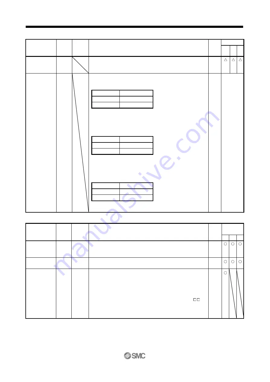
Gain changing
CDP
The values of the load to motor inertia moment ratio and the gains are
changed to the value set in parameter No. PB29 to PB34 by turning CDP
on.
DI-1
Control change
LOP
<Position/internal speed control change mode>
Used to select the control mode in the position/internal speed control
change mode.
DI-1
Refer to
Functions/A
pplications.
(Note) LOP
Control mode
0
Position
1
Internal speed
Note. 0: off
1: on
<Internal speed/internal torque control change mode>
Used to select the control mode in the internal speed/internal torque
control change mode.
(Note) LOP
Control mode
0
Internal speed
1
Internal torque
Note. 0: off
1: on
<Internal torque/position control mode>
Used to select the control mode in the internal torque/position control
change mode.
(Note) LOP
Control mode
0
Internal torque
1
Position
Note. 0: off
1: on
(b) Output devices
Device
Symbol
Connec-
tor pin
No.
Functions/Applications
I/O
division
Control
mode
P
S
T
Trouble
ALM
CN1-9
ALM turns off when power is switched off or the protective circuit is
activated to shut off the base circuit.
When there is no alarm, ALM turns on approximately 1s after power-on.
DO-1
Ready
RD
CN1-11 RD turns on when the servo motor is ready for the operation after turning
on the servo-on (SON).
DO-1
In-position
INP
CN1-10 INP turns on when the number of droop pulses is in the preset in-position
range. The in-position range can be changed using parameter No. PA10.
When the in-position range is increased, may be kept connected during
low-speed rotation.
INP turns on when servo-on turns on.
If parameter No. PA04 (tough drive function selection) is set to " 1 "
and the overload tough drive function is enabled, the INP ON time in the
overload tough drive mode is delayed. The delay time can be limited by
parameter No. PC26 (detailed setting of overload tough drive).
DO-1


