SMAY KWP-P-E Technical Documentation Manual Download Page 5


Technical documentation


KWP-P-E


Version 6.00 
Date of editing: 16.09.2022 r. 

Strona 4 z 35 

where: 

E


 fire integrity, 

I


 fire insulation, 

120

 duration of fulfilment of E, I and S criteria, expressed in minutes, 

v

ew


 damper mounted directly in the wall, 

h

ow


 damper mounted directly in the ceiling, 

v

ed


 damper mounted directly in the duct, 

i

o


 operating effectiveness criteria are fulfilled from the inside to the outside (fire inside), and from 

the outside to the inside (fire outside). 

S


 smoke leakage, 

1500 

 allowable negative pressure in the installation, in pascals, 

C

10000


  the  suitability  of  the  damper  for  use  in  combined  smoke  control  and  general  ventilation 

systems, 

AA


 automatic starting, 

multi 

 acceptable installation in installations serving more than one fire zone. 


KWP-O-E and KWP-O-S fire dampers may be installed in vertical building partitions with both 

horizontal and 

vertical rotation axis 

of baffle, the damper may be rotated in a way enabling on location of actuator on left or 

right side and on top or bottom.  
 

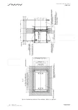
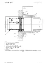
KWP-P-E  fire  dampers  are  intended for  installation  on  internal  and external building partition  and  also  on fire 

ventilation  ducts.  In  case  of external wall  insulation  there  is  required  to  use  the damper with  increased  anti-

corrosion  properties  and  with  finishing  element  (intake  or  launcher),  which  will  protect  from  influence  of 

atmospheric factors. Drive system (actuator or spring mechanism) should be installed inside facility.  

4.


TECHNICAL DESCRIPTION


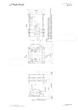
KWP-P-E  fire  dampers  comprise  with  two  steel  housing,  rectangular  in  profile,  separated  by  isolating  divider, 

moving, single-plane baffle and drive mechanism. 


The damper housing and its interacting elements are made of galvanized steel sheet. Both ends of the housing 

are terminated with connection flanges, allowing easy connection between the duct and the damper.  


There  is  intumescent  seal  on  the  inner  surface  of  the  housing,  in  the  place  of  perforation  around  the  closed 

isolating  baffle.  Its  characteristic  feature  is  the  fact  that  their  volume  increases  at  high  temperatures,  tightly 

filling all leaks between the baffle and the body. Between housing and insulating spacer there is foamed rubber 

gasket, ensuring the tightness integrity in the ambient temperature. 


 The  isolating  baffle  of  the  damper  is  made  of  calcium-silica  board,  and  a  aluminum  tape  is  installed  on  its 

perimeter, ensuring reduction of friction. 


Baffle is rotating on two steel axles located in housing. Baffle movement is limited in the closed position by a 

stop bar. 


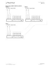
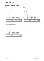
KWP-P-E damper is provided with an electric actuator and BLF, BFL, BFN or BF series return spring by BELIMO, 

constituting  the  damper’s  actuating  system  having  supply  voltage  AC  230V  or  AC/DC  24V. 

After  voltage  is 

supplied, the actuator rotates the baffle into the open position. 


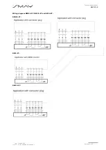
The  actuators  are  moving  in both  directions  by  the  voltage given  to  the  individual  circuits 

  actuators  do  not 

have return spring and thermal fuse. The dampers can be made with an inspection cover in accordance with the 

order code. 
During  normal  operation  of  the  system,  KWP-P-E  dampers  are  in  closed  position.  If  a  fire  breaks  out,  the 

damper’s 

baffle rotates to an open position, or stays closed. 


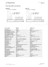
The type series of the dampers covers the following dimensions: clear damper width 

from 200 to 1500 mm


(50 mm intervals) and clear damper height 

from


200 to 1000 mm

 (50 mm intervals), with a maximum cross-

sectional  area  for  KWP-P-E  totals  1,5  m

2

.  Length  of  standard  edition  of  KWP-P-E  damper  is  L=350  [mm] 

(optional L=600 [mm]). 


For special request KWP-P dampers could be made in 10 mm interval dimension.  


Summary of Contents for KWP-P-E

Page 1: ...v a https www smay eu Technical Documentation KWP P E Fire Damper rectangular ...

Page 2: ...ing opening during the test at the right time Automatic starting Pass Response time Closure time Automatic starting Pass Reliability 10 000 cycles 120S Fire resistance Fire integrity E Fire insulation l Smoke leakage S Mechanical stability under E Maintenance of the cross section under E EI 120 vew how i o S1500C10000 AAmulti EI 120 ved i o S1000C10000 AAmulti Durability Maintenance of certainty o...

Page 3: ...EGULATIONS 3 3 INTENDED USE 3 4 TECHNICAL DESCRIPTION 4 5 BELIMO ELECTRIC ACTUATORS USED IN KWP P E 7 6 CONDITIONS OF TRANSPORT AND STORAGE 14 7 INSTALLATION TECHNOLOGY 14 7 1 INSTALLATION TECHNOLOGY RIGID WALL 15 7 2 INSTALLATION TECHNOLOGY CEILING 19 7 3 INSTALLATION TECHNOLOGY DUCT 21 8 INSTALLATION TECHNOLOGY FOR FIRE DAMPERS IN BATTERIES 22 9 PRINCIPLES OF MAINTENANCE 33 10 TERMS OF WARRANTY ...

Page 4: ...mpers are designed to be used in automatically activated fire ventilation system to support both single fire zones and multiple fire zones They are installed also in mixed type ventilation system where they are performing the function of fire ventilation and general comfort ventilation systems In fire ventilation systems starting the fans follows after the damper goes to right position open positi...

Page 5: ...alvanized steel sheet Both ends of the housing are terminated with connection flanges allowing easy connection between the duct and the damper There is intumescent seal on the inner surface of the housing in the place of perforation around the closed isolating baffle Its characteristic feature is the fact that their volume increases at high temperatures tightly filling all leaks between the baffle...

Page 6: ...na 5 z 35 Table 2 Type series of damper dimension KWP P E BEN actuators are used for the damper clear area of P 1 2 m2 BEE actuators are used for the damper clear area of 1 2 m2 P 1 3 m2 and when H 1200 mm BE actuators are used for the damper clear area P 1 3 m2 or when H 1200 mm ...

Page 7: ...g 16 09 2022 r Strona 6 z 35 Figure 1 KWP P E damper Notes 1 If H 250 then B 125 A H 125 C1 40 2 If H 250 then A B H 2 C1 H 8 2 80 3 If H 550 then A B H 2 C1 H 8 2 80 C2 H 8 2 270 4 For BLE D B 110 for BE actuator D B 125 Depth of fastening in wall construction ...

Page 8: ... 3 52 5 56 7 61 0 65 2 75 9 80 4 85 0 800 29 6 34 3 38 8 43 5 48 1 52 8 57 4 62 1 66 7 71 3 82 8 87 7 92 7 900 32 1 37 1 42 1 47 2 52 2 57 3 62 3 67 4 72 4 77 5 89 6 96 2 101 5 1000 40 1 45 5 51 0 56 4 61 9 67 4 72 8 78 2 83 7 97 8 103 6 109 3 1100 43 2 48 9 54 8 60 7 66 5 72 4 78 2 84 1 90 2 104 6 1200 46 2 52 3 58 7 64 9 71 1 77 5 83 7 90 0 104 5 1300 61 6 68 6 75 6 82 6 89 6 97 8 104 4 1400 65 ...

Page 9: ...Technical documentation KWP P E Version 6 00 Date of editing 16 09 2022 r Strona 8 z 35 Wiring diagram BEN230 BEE230 and BE230 BEN230 BE230 BEE230 ...

Page 10: ...Technical documentation KWP P E Version 6 00 Date of editing 16 09 2022 r Strona 9 z 35 Wiring diagram BEN24 BEE24 and BE24 BEN24 BE24 BEE24 ...

Page 11: ...Technical documentation KWP P E Version 6 00 Date of editing 16 09 2022 r Strona 10 z 35 Wiring diagram BEN24 ST BEE24 ST and BE24 ST BEN24 ST BE24 ST BEE24 ST ...

Page 12: ...Technical documentation KWP P E Version 6 00 Date of editing 16 09 2022 r Strona 11 z 35 Wiring diagram BEN24 SR and BEE24 SR BEN24 SR BEE24 SR Technical data BEN230 BEN24 ST ...

Page 13: ...Wersja 1 00 Data edycji 16 09 2022 r Strona 12 z 35 Dokumentacja techniczno ruchowa KWP P E Technical data BEE230 BEE24 ST ...

Page 14: ...Wersja 1 00 Data edycji 16 09 2022 r Strona 13 z 35 Dokumentacja techniczno ruchowa KWP P E Technical data BE230 BE24 ST ...

Page 15: ...nent damage not covered by the warranty Before installing secure the fire damper by dust and dirt using a foil or other screening material It can prevent components of fire damper by damage ATTENTION Distance between fire dampers or fire damper and construction elements must be compatible with standard 1366 2 Minimal 200 mm between fire damper which are installed in different ventilating wires Min...

Page 16: ...s possible to use mounting brackets paying attention to the immobilization of the damper 7 1 INSTALLATION TECHNOLOGY RIGID WALL f Make an opening in the wall with the 100 mm acceptable 80 120 mm greater than the nominal dimensions of the fire damper B 100 and H 100 g Put the closed fire damper into the installation opening on the depth marked by undercuts on the damper body dimension 60 mm from on...

Page 17: ...Wersja 1 00 Data edycji 16 09 2022 r Strona 16 z 35 Dokumentacja techniczno ruchowa KWP P E Figure 4 Installation method of fire dampers KWP O in rigid wall ...

Page 18: ...ja 1 00 Data edycji 16 09 2022 r Strona 17 z 35 Dokumentacja techniczno ruchowa KWP P E Figure 5 Installation method of the damper in rigid wall with one sidedly connected self supporting smoke extract duct ...

Page 19: ... edycji 16 09 2022 r Strona 18 z 35 Dokumentacja techniczno ruchowa KWP P E Figure 6 Installation method of the damper in rigid wall with one sidedly connected self supporting smoke extract duct connected on both sides ...

Page 20: ...tem 1 d Mount the mounting brackets properly Side length up to 500 mm 1 pcs Side length from 500 to 800 mm 2 pcs e Make the duct with 50 mm thick PROMATECT L500 panels item 3 f Make a band around the duct with 50 mm thick 60 mm width PROMATECT L500 panels item 4 g Make a band around the duct under ceiling with 20 mm thick 200 mm width PROMATECT H item 5 This band is required only when mineral wool...

Page 21: ...ct with sealing of cement mortar Actuator under ceiling Actuator above ceiling E mm Thickness of ceiling 28 96 For ceiling with thickness greater than 150 mm connect the damper to the duct before the damper isolation with cement mortar the damper frame will be bricked up along with a part of the duct Figure 9 Proposed dimensions of mounting brackets for installation in a ceiling ...

Page 22: ...A 06 0218 and PROMAT guidelines Figure 10 Installation method of dampers on the tee 1 Promatect L 500 board with thickness of 50mm 2 Insulation of PROMATECT H board with minimal thickness of 10mm 3 Insulation of PROMATECT H board with thickness of 25mm 4 The support rail must take into account the magnitude of the load 5 Connection in accordance with the standard of the supplier of the ventilation...

Page 23: ... dampers assembly strips and complete set of self tapping screws The purchase of other materials needed such as intumescent gasket PROMASEAL PL PVC SK mineral wool for thermal insulation with minimum density of 60 kg m3 and aluminum tape remains with the Customer The secund variant provides for supply by the Manufacturer of complete set of fire dampers and all the elements needed for installation ...

Page 24: ...le free space between the fire dampers as shown in w1 NOTE The alternative way of wool mounting is to use two layers of wool with thickness of 30 mm In this case apply the fire resistant PROMASTOP Coating with width of 50 mm The mass is placed between the strips of wool and between wool and damper housings c Place the fire damper A on the fire damper B and assemble them together on the front and b...

Page 25: ...ative way of wool mounting is to use two layers of wool with thickness of 30 mm In this case apply the fire resistant PROMASTOP Coating with width of 50 mm The mass is placed between the strips of wool and between wool and damper housings c Place the fire damper B on the fire damper C and assemble them together on the front and back with use of perforated assembly strips 2 and self tapping screws ...

Page 26: ...to the openings in fire damper body In order to carry out the correct assembly 4 self tapping screws should be used per each assembly strip with length of 1200 mm c Fill the whole free space between the joint of fire dampers with non combustible mineral wool as shown in w1 NOTE The alternative way of wool mounting is to use two layers of wool with thickness of 30 mm In this case apply the fire res...

Page 27: ...D STEP 1 a Fix the gasket on insulating spacer of one of adjoining fire dampers position 1 in the Figure 14 b Set together the sides of fire damper A and the fire damper B where the gasket was fixed and assemble them together on the front and back with use of perforated assembly strips 2 and self tapping screws M6x10 3 which should be tightened into the openings in fire damper body In order to car...

Page 28: ...battery size and its arrangement For vertical battery consisting of two KWP fire dampers B1 120 x H1 H2 180 Figure 15 For vertical battery consisting of three KWP fire dampers B1 120 x H1 H2 H3 240 Figure 16 For horizontal battery consisting of two KWP fire dampers B1 B2 180 x H1 120 Figure 17 For battery consisting of four KWP fire B1 B2 180 x H1 H2 180 Figure 18 b Put the battery of fire dampers...

Page 29: ...Wersja 1 00 Data edycji 16 09 2022 r Strona 28 z 35 Dokumentacja techniczno ruchowa KWP P E Figure 4 Installation of a battery consisting of two fire dampers KWP in vertical arrangement in ceiling ...

Page 30: ...Wersja 1 00 Data edycji 16 09 2022 r Strona 29 z 35 Dokumentacja techniczno ruchowa KWP P E Figure 58 Installation of a battery consisting of three fire dampers KWP in vertical arrangement in ceiling ...

Page 31: ...Wersja 1 00 Data edycji 16 09 2022 r Strona 30 z 35 Dokumentacja techniczno ruchowa KWP P E Figure 69 Installation of battery consisting of two fire dampers KWP in horizontal arrangement in ceiling ...

Page 32: ...Wersja 1 00 Data edycji 16 09 2022 r Strona 31 z 35 Dokumentacja techniczno ruchowa KWP P E Figure 20 Installation of a battery consisting of four fire dampers KWP in ceiling ...

Page 33: ... 3 175 0 400 53 9 63 8 73 7 83 0 92 6 98 0 112 7 122 6 131 9 141 8 152 0 177 7 188 5 199 1 500 72 2 83 5 94 1 105 5 116 2 127 5 138 5 149 9 160 2 171 2 199 8 211 5 223 2 600 80 2 92 6 104 7 117 1 129 2 142 0 154 1 166 5 178 9 191 3 222 0 235 5 248 7 700 88 4 102 0 115 2 14 9 142 9 156 8 163 1 176 0 197 3 211 1 247 6 264 9 282 5 800 96 6 111 8 125 8 141 3 155 9 170 9 186 1 200 7 215 7 230 6 266 0 2...

Page 34: ...of the KWP P E fire damper when running the system it is recommended to carry out regular checks and record them as shown in table below It is recommended to repeat checks at intervals or at least once every 6 months Table 4 Recommended checks Fire damper type Control date Check actuator wiring condition if doesn t damaged Check limit switch wiring condition if doesn t damaged Check cleanliness in...

Page 35: ...leaned with generally available cleaners Do not use aggressive caustic cleaners and sharp tools Table 5 Diagnostic card Diagnostic card No Symptoms of malfunction Causes of malfunction How to remove malfunction 1 No signaling opening closing fire damper 1 Failure to fully open the baffle wrong connected ventilation duct 2 Improperly connected wires of limit switch 3 Damaged actuator 1 Removing the...

Page 36: ...d to be defective together with a detailed description of the technical problem and documents confirming the performance of any inspection provided by the manufacturer and periodic maintenance c The manufacturer undertakes to remove the defect within 2 working days of receiving the notification The manufacturer undertakes to remove the defect within 21 working days from the date of receipt of the ...

Reviews: