background image


HAT833 Series Three Power ATS Controller User Manual                                                        Page 54 of 56 


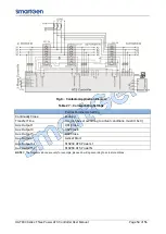
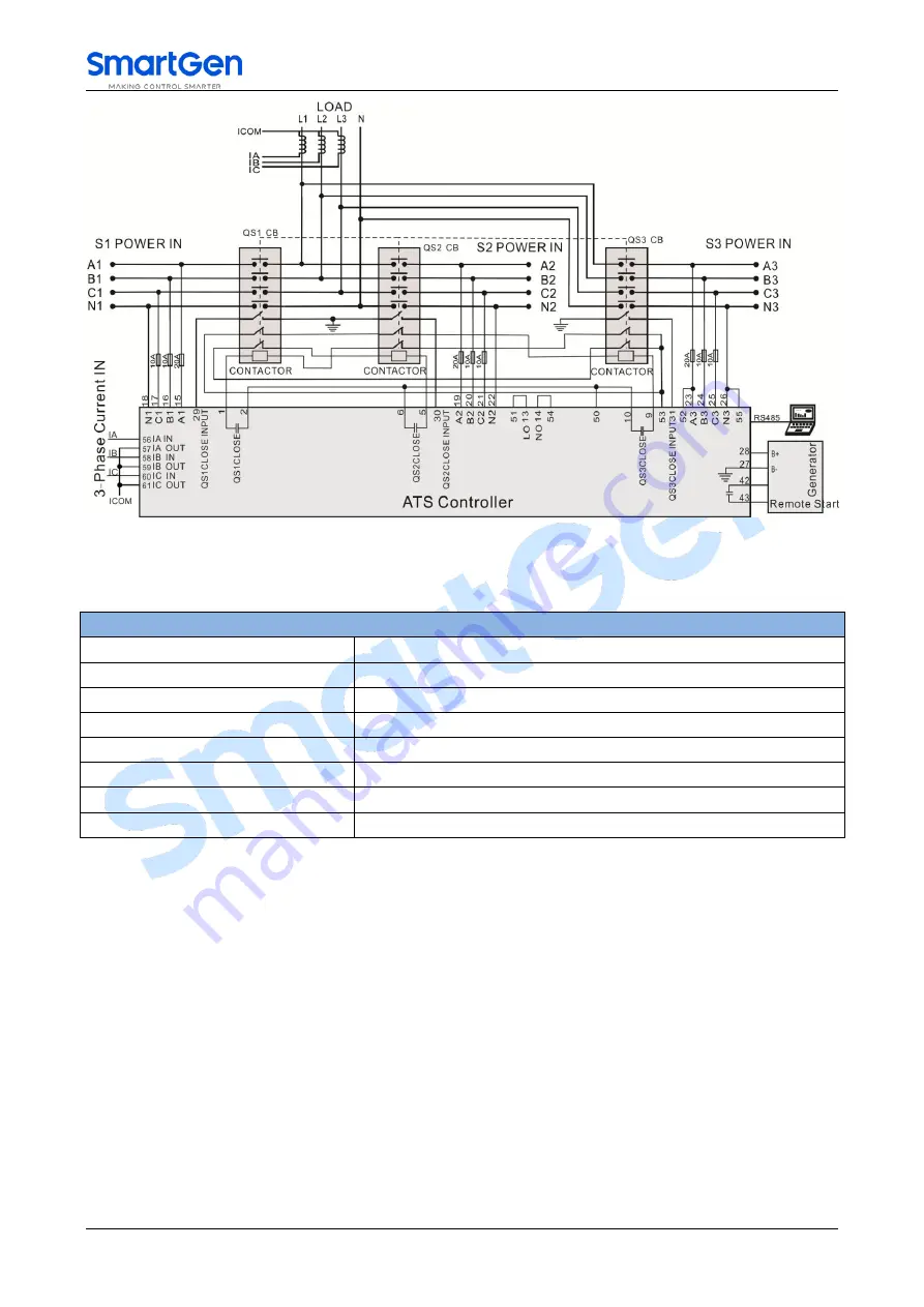
Fig.8 – Contactor Application Diagram 

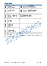
Table 27 – Corresponding Settings 

Partial Parameters Setting 

Continually Close 

Enabled 

Transfer Time 

10s (can be set according to actual conditions, mustn’t be 0) 

Aux. Output 1 

QS1 Close 

Aux. Output 3 

QS2 Close 

Aux. Output 5 

QS3 Close 

Aux. Output 7 

Genset Start 

Aux. Output 11 

S1S2S3 ATS Power L1 

Aux. Output 12 

S1S2S3 ATS Power N 

NOTE 7: 

The diagrams above are only for example, please do wiring according to actual conditions. 


Summary of Contents for HAT833 Series

Page 1: ...HAT833 HAT833 HAT833S THREE POWER ATS CONTROLLER USER MANUAL ...

Page 2: ...ss above Any reference to trademarked product names used within this publication is owned by their respective companies SmartGen Technology reserves the right to change the contents of this document without prior notice Table 1 Software Version Date Version Note 2018 10 16 1 0 Original release 2018 12 13 1 1 Modified controller front panel picture 2020 02 13 1 2 Modified typical application diagra...

Page 3: ...MOTE START STOP 21 8 2 AUTO START STOP 21 8 2 1 START CONDITIONS 21 8 2 1 1 INPUT START 21 8 2 1 2 GEN START MAINS NG 21 8 2 1 3 GEN START MASTER 21 8 2 2 GEN GEN START STOP 21 8 2 3 SCHEDULED RUN 24 8 2 4 SCHEDULED NOT RUN 24 9 PARAMETERS CONFIGURATION 25 9 1 ILLUSTRATION 25 9 2 PARAMETERS TABLE 25 9 3 DIGITAL INPUT OUTPUT FUNCTION DESCRIPTION 36 9 3 1 INPUT PORTS FUNCTION 36 9 3 2 OUTPUT PORTS F...

Page 4: ...ree Power ATS Controller User Manual Page 5 of 56 14 2 AUTO OPERATION 48 14 3 MANUAL OPERATION 48 15 COMMUNICATION CONFIGURATION 49 16 TERMINALS 50 17 TYPICAL WIRING DIAGRAM 53 18 INSTALLATION 55 19 TROUBLE SHOOTING 56 ...

Page 5: ...TS The powerful microprocessor contained within the unit allows for precision voltage 3 way 3 phase measuring and make accurate judgment and the corresponding volt free digital output port will active when there is over under voltage over under frequency loss of phase phase sequence wrong and other abnormal condition occurs It has compact structure advanced circuits simple wiring and high reliabil...

Page 6: ...Page 7 of 56 2 NAMING CONVENTION AND MODEL COMPARISON 2 1 NAMING CONVENTION Fig 1 Naming Convention 2 2 MODEL COMPARISON Table 2 Model Comparison Functions Model DC Supply AC Supply Sync Closing Input Port No Output Port No RS485 HAT833 8 12 HAT833S 8 12 ...

Page 7: ...ts for HAT833S With parallel fault detection function It will send alarm when any two switches parallel time is over 300ms and open the last closed breaker All parameters can be set on site Passwords authentication ensures authorized staff operation only The genset can be manual test on site to achieve start stop operation Automatic re closing Closing output signal can be set as pulse or continuou...

Page 8: ...tput 1 6 Relay Capacity 16A AC250V Volts free output Programmble Output 7 12 Relay Capacity 8A AC250V Volts free output Digital Input GND B connect is active Communication 1 Dual RS485 isolated interface MODBUS Protocol 2 D type USB port Case Dimensions 260mmx180mmx54mm Panel Cutout 242mmx161mm Working Temperature 25 70 C Working Humidity 20 93 RH Storage Temperature 25 70 C Protection Level IP65 ...

Page 9: ...al Apparent Power kVA 12 Load 3 Phase Power Factor PF 13 Load Average Power Factor PF 14 Continuous Power Supply Time Currently 15 Continuous Power Supply Time Last Time 16 S1 Total Power Supply Time 17 S2 Total Power Supply Time 18 S3 Total Power Supply Time 19 S1 Total Active Energy kWh 20 S2 Total Active Energy kWh 21 S3 Total Active Energy kWh 22 S1 Total Reactive Energy kvarh 23 S2 Total Reac...

Page 10: ...urs Man Light on when the module is in Manual mode Auto Light on when the module is in Auto mode Alarm Mute Light on when alarm mute IOO Illuminated QS1 closed S1 supply power for load Flashing status switching OIO Illuminated QS2 closed S2 supply power for load Flashing status switching OOI Illuminated QS3 closed S3 supply power for load Flashing status switching OOO Illuminated QS1 QS2 QS3 all o...

Page 11: ...mode and Auto mode switching Alarm Reset Pressing this key can reset fault alarm Return Homepage When setting parameters press the key to return back In main screen press the key to return the first screen in other screen press the key to return to main screen Set Confirm In main screen press the key to enter to menu In menu screen press this key can move cursor and confirm setting information Up ...

Page 12: ...frequency phase angle S3 total supply time Genset start Status Load 3 phase current I1 I2 I3 3 Phase Active Power kW P1 P2 P3 3 Phase Reactive Power Q1 Q2 Q3 3 Phase Apparent Power KVA S1 S2 S3 Total Active Power kW sum of P1 P2 P3 Total Reactive Power kvar sum of Q1 Q2 Q3 Total Apparent Power KVA sum of S1 S2 S3 3 Phase Power Factor PF PF1 PF2 PF3 Average Power Factor PF average of PF1 PF2 PF3 Co...

Page 13: ...tage is higher than the set value 6 S1 Under Volt Voltage has fallen below the set value 7 S1 Over Freq Frequency is higher than the set value 8 S1 Under Freq Frequency has fallen below the set value 9 S1 Loss of Phase Loss of one phase or two phase of A B and C 10 S1 Phase Seq Wrong A B C phase sequence is wrong Table 9 S2 Voltage Status No Item Description 1 S2 Available S2 Normal Delay 2 S2 Una...

Page 14: ...n countdown will be terminated when cycle start is active 7 S3 Cycle Run S3 cycle run countdown will be terminated when cycle start is active 8 S1 Genset Working Active only when system has 2 gensets and S1 generating 9 S2 Genset Working Active only when system has 2 gensets and S2 generating 10 S3 Genset Working Active only when system has 2 gensets and S3 generating 11 Genset Working Genset star...

Page 15: ...onfirm QS1 PF Input signal is active 20 Waiting QS2 PF Before QS2 is closed it s the delay time to confirm QS2 PF Input signal is active 21 Waiting QS3 PF Before QS3 is closed it s the delay time to confirm QS3 PF Input signal is active 22 Elevator Delay Elevator control output before ATS transfer 23 S1 On Load QS1 was already closed and S1 is taking load 24 S2 On Load QS2 was already closed and S...

Page 16: ...king load and its current has exceeded the pre set value and the action select Trip it will initiate a trip alarm 9 S3 Over Current Trip When the S3 is taking load and its current has exceeded the pre set value and the action select Trip it will initiate a trip alarm 10 Forced Open Fault When the input is active and the action cut off non fire supply select Fault it will initiate a fault alarm 11 ...

Page 17: ...5 Panel Locked The information displays when panel lock is active and keys are pressed Manual Auto IOO OIO OOI OOO and Test keys Table 16 Other Status Information No Item Description 1 Start Inhibit Genset start Inhibit is active 2 S1 Load Inhibit S1 Load Inhibit input is active 3 S2 Load Inhibit S2 Load Inhibit input is active 4 S3 Load Inhibit S3 Load Inhibit input is active 5 NEL 1 Trip NEL1 of...

Page 18: ...T833S 8 About Press Up Down key to choose parameters the current line was highlighted with black and then press Confirm key to enter into the corresponding display screen NOTE 1 Default password is 01234 user can change it in case of others change the parameters setting Please clearly remember the password after changing If you forget it please contact SmartGen services NOTE 2 Data Calibration is ...

Page 19: ...nual start stop menu interface is as follows Manual Test Genset Press Up Down key to choose parameters the current line was highlighted with black and then press Confirm key to confirm Return S1 Genset Stop S1 Genset Start S2 Genset Stop S2 Genset Start When system is S1 Gens S2 Mains S3 Gens manual start stop menu interface is as follows Manual Test Genset Press Up Down key to choose parameters t...

Page 20: ...nd remote start stop signals using MODBUS protocol via RS485 port Remote Stop Disconnect the start signal i e stop the running genset Remote Start Output the start signal i e start the genset 8 2 AUTO START STOP 8 2 1 START CONDITIONS 8 2 1 1 INPUT START Set input port as Remote Start On Load or Remote Start Off Load both could not be set simultaneously Remote Start on Load When the input is activ...

Page 21: ...rts after the preset S1 cycle run delay has expired and the S2 loading process is same as S1 S1 will stop automatically after the S2 has taken load successfully S1 and S2 will cycle run in this way alternately until the remote start signal deactivated During the start process if there is genset fault alarm genset fault delay overtime or genset fault input is active fail to close or load inhibit al...

Page 22: ...ens S2 Gens S3 Mains the output should be set as S1 Genset Start and S2 Genset Start if system is S1 Gens S2 Mains S3 Gens the output should be set as S1 Genset Start and S3 Genset Start if system is S1 Mains S2 Gens S3 Gens the output should be set as S2 Genset Start and S3 Genset Start if system is S1 Gens S2 Gens S3 Gens the output should be set as S1 Genset Start S2 Genset Start and S3 Genset ...

Page 23: ...ed Run can be set as start monthly weekly and daily Run Monthly Which month to start start date and time can be set Run Weekly Can start the genset at the same time in couple days of a week Eg Start the genset at 8 00 a m from Monday to Friday and keep 10 hours Run Daily Can start the genset at same time everyday 8 2 4 SCHEDULED NOT RUN Once Scheduled Not Run enables users can set the Scheduled No...

Page 24: ...l 0 3600 s 10 The delay from S1 voltage abnormal to normal 2 S1 Volt Abnormal 0 3600 s 5 The delay from S1 voltage normal to abnormal 3 S2 Volt Normal 0 3600 s 10 The delay from S2 voltage abnormal to normal 4 S2 Volt Abnormal 0 3600 s 5 The delay from S2 voltage normal to abnormal 5 S3 Volt Normal 0 3600 s 10 The delay from S3 voltage abnormal to normal 6 S3 Volt Abnormal 0 3600 s 5 The delay fro...

Page 25: ...e 20 Rated Frequency 10 0 75 0 Hz 50 0 Rated frequency of AC system 21 Over Frequency Warn 0 1 1 0 Disable 1 Enable 22 Set Value 0 200 110 Upper limit value of frequency it is abnormal if the value has exceeded the set value 23 Return Value 0 200 104 Upper limit return value of frequency it is normal only when the value has fallen below the set value 24 Under Frequency Warn 0 1 1 0 Disable 1 Enabl...

Page 26: ...en Delay 0 20 0 s 0 0 When the breaker fail to close for the first time then the module will open for the second time and the Again Open Delay begins after the delay has expired if still failed to close for the second time the module will send out fail to close alarm 11 Forced Open Action 0 1 0 0 Warn Alarm 1 Fault Alarm 12 Continually Close 0 1 0 0 Disable 1 Enable If Enable is selected Close Tim...

Page 27: ... when the delay ends it will initiate a closing failure alarm or opening failure alarm Generator 1 Start Delay 0 9999 s 1 When the genset is ready to start start delay begins after the start delay has expired start signal will be initiated 2 Stop Delay 0 9999 s 5 When the genset is ready to stop stop delay begins after the stop delay has expired stop signal will be initiated 3 Gen Gen Start Mode 0...

Page 28: ...Limit 0 100 80 The max loading power of S1 genset used for power scheduling 16 S1 Power Scheduling Lower Limit 0 100 30 The mmin loading power of S1 genset used for power scheduling 17 S2 Power Scheduling Upper Limit 0 100 80 The max loading power of S2 genset used for power scheduling 18 S2 Power Scheduling Lower Limit 0 100 30 The mmin loading power of S2 genset used for power scheduling 19 S3 P...

Page 29: ...ly 2 Daily 12 Time Month 1 4095 4095 Bit0 Jan Bit1 Feb Bit2 Mar Bit3 Apr Bit4 May Bit5 June Bit6 July Bit7 Aug Bit8 Sep Bit9 Oct Bit10 Nov Bit11 Dec 13 Time Day 1 31 1 The date of NOT start the genset 14 Time Week 1 127 1 Bit0 Sunday Bit1 Monday Bit2 Tuesday Bit3 Wednesday Bit4 Thursday Bit5 Friday Bit6 Saturday 15 Time Hour 0 23 0 The time of NOT start the genset 16 Time Minute 0 59 0 17 Duration...

Page 30: ...s the over current delay time when Definite Time is selected 16 IDMT Delay Multiply 1 36 36 It s the over current multiply when IDMT is selected 17 NEL Trip 0 1 0 0 Disable 1 Enable 18 NEL1 Set Value 0 200 90 Off load output will active if the load power has exceeded the set value and the delay time has expired 19 NEL1 Delay 0 3600 s 5 20 NEL2 Set Value 0 200 100 Off load output will active if the...

Page 31: ...t NO 1 Output NC 2 Contents Setting 0 107 34 QS1 Close Control 3 Relay Output 2 0 1 0 0 Output NO 1 Output NC 4 Contents Setting 0 107 35 QS1 Open Control 5 Relay Output 3 0 1 0 0 Output NO 1 Output NC 6 Contents Setting 0 107 36 QS2 Close Control 7 Relay Output 4 0 1 0 0 Output NO 1 Output NC 8 Contents Setting 0 107 37 QS2 Open Control 9 Relay Output 5 0 1 0 0 Output NO 1 Output NC 10 Contents S...

Page 32: ...Type 0 1 1 0 Output NO 1 Output NC 30 Combined 1 And Out Contents Setting 0 107 0 Not Used 31 Combined 2 Or Out 1 Active Type 0 1 0 0 Output NO 1 Output NC 32 Combined 2 Or Out 1 Contents Setting 0 107 0 Not Used 33 Combined 2 Or Out 2 Active Type 0 1 0 0 Output NO 1 Output NC 34 Combined 2 Or Out 2 Contents Setting 0 107 0 Not Used 35 Combined 2 And Out Active Type 0 1 0 0 Output NO 1 Output NC 3...

Page 33: ...ed 51 Combined 5 Or Out 2 Active Type 0 1 0 0 Output NO 1 Output NC 52 Combined 5 Or Out 2 Contents Setting 0 107 0 Not Used 53 Combined 5 And Out Active Type 0 1 0 0 Output NO 1 Output NC 54 Combined 5 And Out Contents Setting 0 107 0 Not Used 55 Combined 6 Or Out 1 Active Type 0 1 0 0 Output NO 1 Output NC 56 Combined 6 Or Out 1 Contents Setting 0 107 0 Not Used 57 Combined 6 Or Out 2 Active Typ...

Page 34: ... 3 2 0 2400bps 1 4800bps 2 9600bps 3 19200bps 6 RS485 1 Stop Bit 1 2 2 2 stop bits or 1 stop bit can be set 7 RS485 2 Baud 0 3 2 0 2400bps 1 4800bps 2 9600bps 3 19200bps 8 RS485 2 Stop Bit 1 2 2 2 stop bits or 1 stop bit can be set 9 Date and Time 10 Controller Description 1 0 20 characters About information is displayed Any characters can be inputted via PC software letter occupies 1 character Ch...

Page 35: ... if the genset is running users should stop it manually then the manual start signal will be deactivated 8 Breaker Trip Input Trip failure input 9 S1 Close Inhibit In Manual mode S1 manual close is inhibited if breaker already closed users should open it manually In Auto mode if breaker already closed then close relay will deactivated or S2 take load 10 S2 Close Inhibit In Manual mode S2 manual cl...

Page 36: ...ntroller to non parallel mode 36 Manual Parallel Parallel is executed as controller in manual close 37 Simulate KEY OOO Same function with Panel OOO Key Please use reset key to control ATS to transfer to OOO 38 Simulate KEY OOI Same function with Panel OOI Key Please use reset key to control ATS to transfer to OOI 39 Simulate KEY IOO Same function with Panel IOO Key Please use reset key to control...

Page 37: ...levator Control Output before the load disconnect or switch transfer Used for control the running elevator stop at the nearest floor until the switch transfer is terminated 20 Reserved 21 S3 Available Output when S3 power is normal 22 S3 Unavailable Output when S3 power is normal 23 S1 Available Output when S1 power is normal 24 S1 Unavailable Output when S1 power is abnormal 25 S2 Available Outpu...

Page 38: ...ly 50 Reserved 51 Reserved 52 S1S2S3 ATS PowerN 53 Remote Control Control the output via RS485 command 54 Input 1 Status Aux Input status 55 Input 2 Status 56 Input 3 Status 57 Input 4 Status 58 Input 5 Status 59 Input 6 Status 60 Input 7 Status 61 Input 8 Status 62 Reserved 63 Reserved 64 S1 Blackout S1 power supply status 65 S1 Over Volt 66 S1 Under Volt 67 S1 Over Freq 68 S1 Under Freq 69 S1 Lo...

Page 39: ...dule Run Output during the Schedule Run process 89 Reserved 90 QS1 QS2 Parallel Alarm QS1 QS2 parallel alarm outputs 91 QS1 QS3 Parallel Alarm QS1 QS3 parallel alarm outputs 92 QS2 QS3 Parallel Alarm QS2 QS3 parallel alarm outputs 93 Reserved 94 Reserved 95 Reserved 96 Reserved 97 Reserved 98 S3 Blackout S3 power supply status 99 S3 Over Volt 100 S3 Under Volt 101 S3 Over Freq 102 S3 Under Freq 10...

Page 40: ...ontents of OR condition output SW1 input port 1 is active Close when OR condition output SW1 is active inactive close when active disconnect when inactive Contents of OR condition output SW2 input port 2 is active Close when OR condition output SW2 is active inactive close when active disconnect when inactive Contents of AND condition output SW3 input port 3 is active Close when AND condition outp...

Page 41: ...rent overcurrent value has corresponding delay Inverse Definite Minimum Time IDMT overcurrent delay decrease with the increase of overcurrent Different overcurrent value has corresponding delay IDMT formula T t IA IT 1 2 T Overcurrent delay second T Timing multiplier ratio IA Current max load current L1 L2 L3 IT Overcurrent setting value Example t 36 IA 550A IT 500A Conclusion T 3600s 1 hour ...

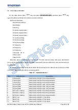
Page 42: ...amount exceeds 200 Event log type includes Action Event Warn Event and Fault Event All fault event actions are fault alarm while all warn event actions are warning alarm Table 21 Action Events List No Action Events Description 1 Closing QS1 Record when the QS1 close relay activated 2 Closing QS2 Record when the QS2 close relay activated 3 Closing QS3 Record when the QS3 close relay activated 4 Ope...

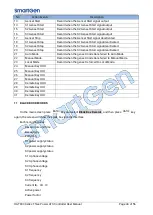
Page 43: ... Start signal deactivated 21 Auto Mode Record when the genset mode transferred to Auto Mode 22 Manual Mode Record when the genset mode transferred to Manual Mode 23 Local Mode Record when the genset is forced to Local Mode 24 Manual Key OOO 25 Manual Key IOO 26 Manual Key OIO 27 Manual Key OOI 28 Remote Key OOO 29 Remote Key IOO 30 Remote Key OIO 31 Remote Key OOI 11 BLACK BOX RECORDS On the main ...

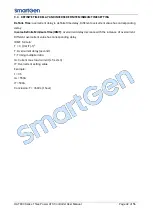
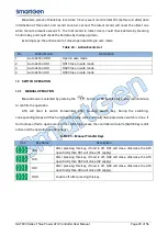
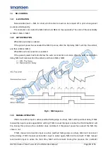
Page 44: ...2 1 MANUAL OPERATION Manual mode is selected by pressing the button a LED besides the button will illuminate to confirm the operation ATS will shart to switch immediately after pressing Switch Key During the switching corresponding lamps will flash and then the lamp will be normally illuminated when switch is done If fail to close or fail to open occurs in the switching process the controller will...

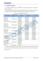
Page 45: ...reaker Status Status IOO QS1 Close QS2 Open QS3 Open Status IOO QS1 Close QS2 Open QS3 Open Status OOI QS3 Close QS1 Open QS2 Open Load Status S1 Supply S1 Supply S3 Supply S1 Abnormal S2 Normal S3 Normal Auto Trans Restore Breaker Status Status OIO QS2 Close QS1 Open QS3 Open Status OIO QS2 Close QS1 Open QS3 Open Status OOI QS3 Close QS1 Open QS2 Open Load Status S2 Supply S2 Supply S3 Supply S1...

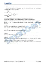
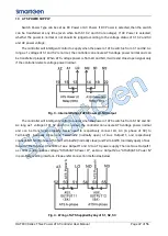
Page 46: ...open signal only if the controller detects voltage power normal Fig 3 Internal Wiring of ATS Power LO NO Output The controller will intelligent control to supply when the power of ATS switch is from S1 S2 and S3 As long as 1 voltage of S1 S2 and S3 is normal the controller can ensure ATS voltage power normal and can be transferred properly Users need to respectively connect LO A3 A phase of S3 to ...

Page 47: ...w the auto reconnection set value after the auto reconnection delay NEL3 will reconnection the earliest and then is NEL2 NEL1 Fig 5 NEL Sequence 14 3 MANUAL OPERATION If NEL manual trip input is active earthed falling edge is active NEL1 will trip without delay If NEL manual trip input is active again NEL2 will trip If NEL manual trip input is active the third time NEL3 will trip During this proce...

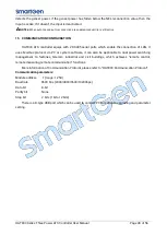
Page 48: ...onnection of LAN It uses Modbus protocol via PC or system software it can also be applicable to dual power switching management to factories telecom industrial and civil buildings which achieves remote control remote measuring remote communication functions More information of Communication Protocol please refer to HAT833 Communication Protocol Communication parameters Module address 1 range 1 254...

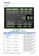
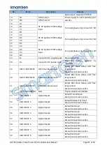
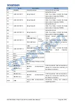
Page 49: ...Default QS1 Open Control Volts free Relay contact Normally Open output Capacity 250V16A 4 5 AUX OUTPUT3 Relay Output3 Default QS2 Close Control Volts free Relay contact Normally Open output Capacity 250V16A 6 7 AUX OUTPUT4 Relay Output4 Default QS2 Open Control Volts free Relay contact Normally Open output Capacity 250V16A 8 9 AUX OUTPUT5 Relay Output5 Default QS3 Close Control Volts free Relay co...

Page 50: ... active 30 QS2 CLOSE INPUT QS2 Close Status Input Detect QS2 close status volts free relay contact Ground connected is active 31 QS3 CLOSE INPUT QS3 Close Status Input Detect QS3 close status volts free relay contact Ground connected is active 32 QS12 CLOSE INPUT Null This terminal is not defined 33 AUX INPUT 1 Digital Intput1 Default Forced Open Ground connected is active 34 AUX INPUT 2 Digital I...

Page 51: ...set Start Normally Closed Volts free Relay contact Normally Open Close output Capacity 250V8A 51 Normally Close 52 Normally Open 53 AUX OUTPUT 12 COM Relay Output12 Default Not Used Volts free Relay contact Normally Open Close output Capacity 250V8A 54 Normally Close 55 Normally Open 56 IA In CT Secondary A Phase current input 57 IA Out 58 IB In CT Secondary B Phase current input 59 IB Out 60 IC I...

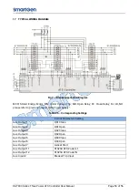
Page 52: ... Close Relay For LO NO please refer to previous chapter ATS Power Supply Table 26 Corresponding Settings Partial Parameters Setting Aux Output 1 QS1 Close Aux Output 2 QS1 Open Aux Output 3 QS2 Close Aux Output 4 QS2 Open Aux Output 5 QS3 Close Aux Output 6 QS3 Open Aux Output 7 Genset Start Aux Output 11 S1S2S3 ATS Power L1 Aux Output 12 S1S2S3 ATS Power N Aux Input 2 Breaker Trip Input ...

Page 53: ...ing Continually Close Enabled Transfer Time 10s can be set according to actual conditions mustn t be 0 Aux Output 1 QS1 Close Aux Output 3 QS2 Close Aux Output 5 QS3 Close Aux Output 7 Genset Start Aux Output 11 S1S2S3 ATS Power L1 Aux Output 12 S1S2S3 ATS Power N NOTE 7 The diagrams above are only for example please do wiring according to actual conditions ...

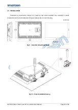
Page 54: ...f 56 18 INSTALLATION Controller is panel built in design it is fixed by clips when installed The controller s overall dimensions and cutout dimensions for panel please refers to as following Unit mm Fig 9 Overall Cutout Dimensions Fig 10 Clips Installation Drawing ...

Page 55: ...y Output Error Check auxiliary output connections pay attention to normally open contact and normally close contact Check the output settings in parameters settings Auxiliary Input Abnormal Ensure that the auxiliary input is soundly connected to GND when it s active while hung up when it is inactive NOTE The input port will be possibly destroyed when connected with voltage Check the input settings...

Reviews: