Hardware Preparation and Installation
RTM-ATCA-747x-10G Installation and Use (6806800S80F)
37
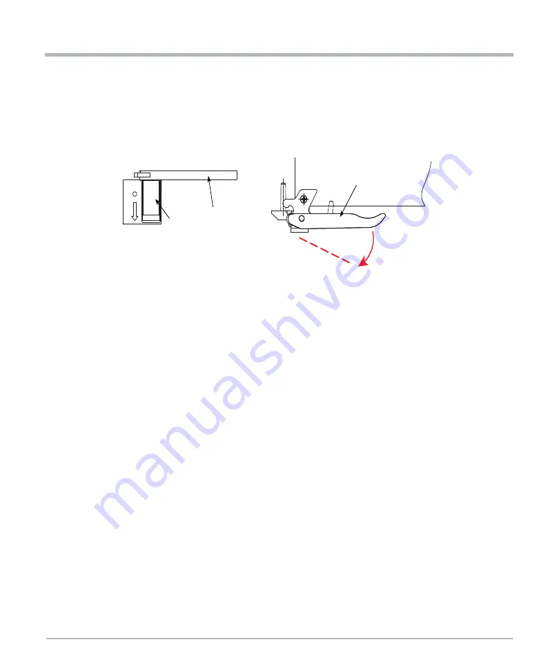
1. Release the lower handle outward by pushing the latch in the direction depicted by the
arrow. By doing that, the handle will be released automatically. The blue LED blinks
indicating that the shelf manager is informed about the desire of the blade to power
down the payload of both the front blade and the RTM and the power-down process is
ongoing
2. Wait until the blue LED of the RTM is permanently ON.
A permanently switched ON LED indicates that the payload of the RTM has been
powered down.
3. Remove interface cables from face plate connectors, if applicable.
4. Loosen the two RTM face plate screws.
5. Release the upper handle, just as in Step 1.
6. Remove the RTM from the slot.
Handle (Top view)
Handle (Front view)
Latch


