36
RTM-ATCA-747x-10G Installation and Use (6806800S80F)
Hardware Preparation and Installation
Hardware Preparation and Installation
3. Insert the RTM into the shelf by placing the top and bottom edges in the card guides of
the slot.
4. Slide the RTM into the slot.
5. Apply equal and steady pressure to the RTM to carefully slide the RTM into the shelf
until you feel resistance. Continue to gently push the RTM until the RTM connectors
engage.
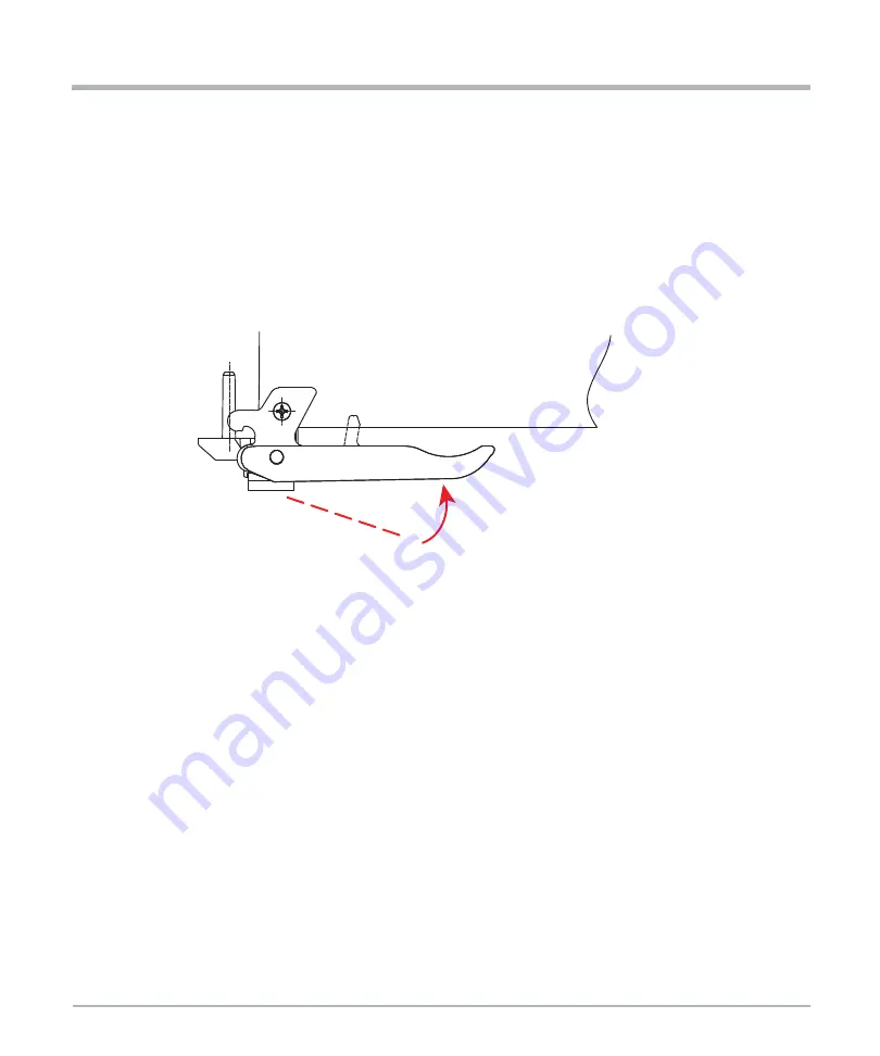
6. Press both handles gently against the RTM’s faceplate. A sound click will be noticed
per each handle, signaling a proper engagement in the shelf.
7. Tighten both face plate screws on the RTM.
8. Wait until the blue LED on the RTM is OFF.
A switched off blue LED indicates that the payload of the RTM has become active.
9. Plug interface cable into face plate connectors, if applicable.
10. Reboot the front blade.
This is necessary so that the OS of the front blade can recognize the SAS controller or
any other PCI device located on the RTM.
2.5.2
Removing the RTM
Removal Procedure
The following procedure describes the removal of the RTM. It assumes that your system is
powered. If your system is unpowered, you can disregard the blue LED and thus skip the
respective step. In this case it is a purely mechanical procedure.


