background image

2000I Installation Guide

8

Powering up the 2000i

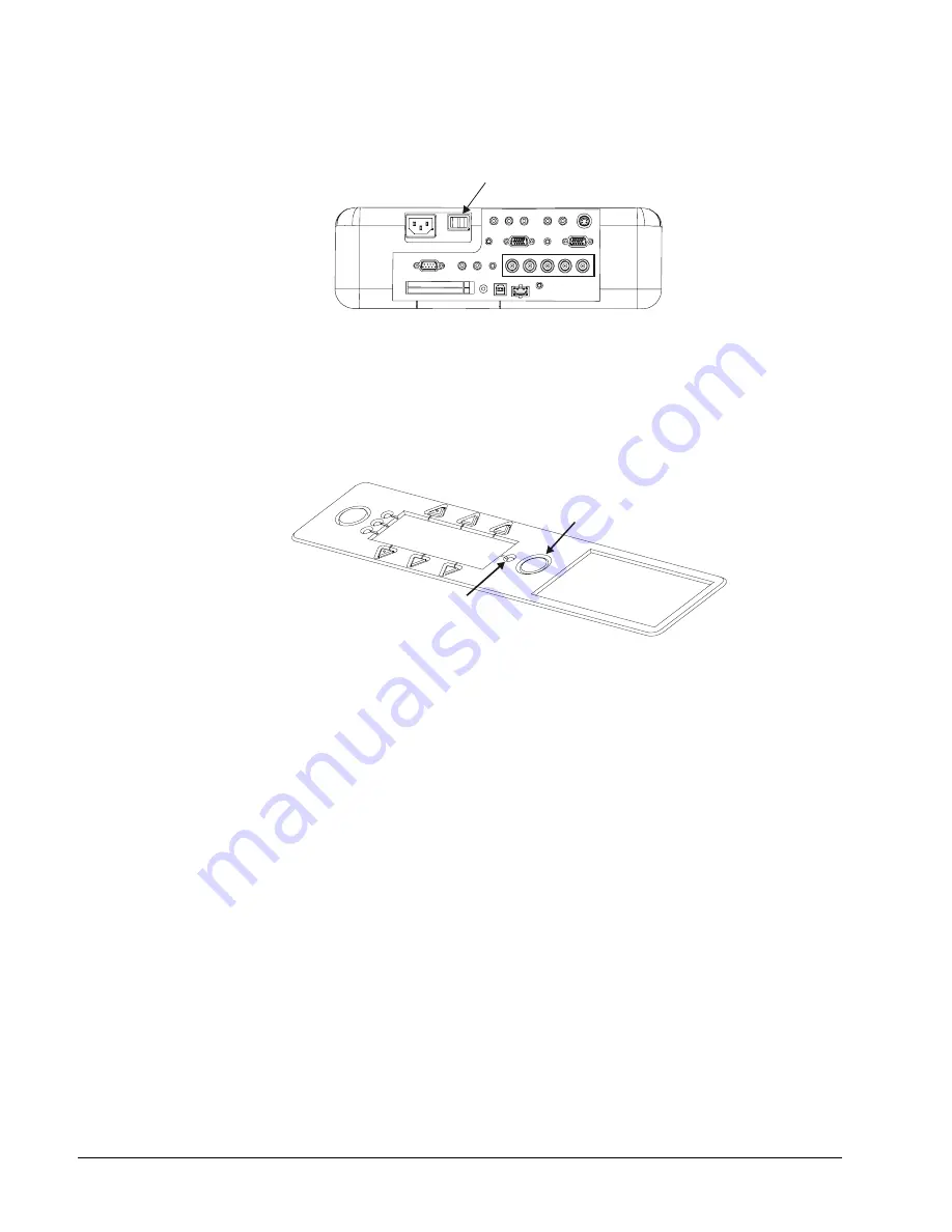
1.  If the projector is not switched on, toggle the main power switch on.

Main Power Switch

Figure 8: Main Power Switch on Projector

2.  At the front of the 2000i, press the power button on the computer.

3.  Turn on the projector lamp by pressing the 

Projector Standby

 button on the Control Panel (to

the right of the pen tray). The LED indicator beside this button should blink fairly quickly for 90
seconds, and then it should remain steadily illuminated when the projector lamp has powered
up.

Projector Standby Button

LED Indicator of
Lamp Status

Figure 9: Projector Standby Button and LED Indicator

OR

Press the Lamp 

On/Off

 button on the projector remote control (or on top of the projector)

to turn on the projector lamp.

After a 30-second lamp warm-up period, the screen displays an image.

You should now adjust the computer power settings and image alignment, install the
SMART Board software CD, configure the COM port, and perform a brief orientation
procedure. To do this, follow the procedures described in the pages that follow.

NOTE

: You should leave the computer and projector main power switch on at all times (so

the projector is either in use, with the lamp illuminated, or in standby mode). However, you
can set the computer to save power during periods of inactivity. The following section
describes how to do this.

Summary of Contents for Board 2000i

Page 1: ...Interactive Whiteboard Guide Installation...

Page 2: ...cations Operation of this equipment in a residential area is likely to cause harmful interference in which case the user will be required to correct the interference at his own expense SMART Board DVi...

Page 3: ...mit hoher Intensit t dar Blicken Sie nicht direkt in den Lichtstrahl Verhindern Sie dass Kinder direkt in den Lichtstrahl blicken WARNING Lock the casters and extend the anti tip feet before you use...

Page 4: ...lients europ ens Le 2000i doit tre utilis uniquement avec les syst mes de distribution d alimentation europ ens TN et TT Le 2000i ne convient pas aux syst mes de distribution d alimentation plus ancie...

Page 5: ...ly ship it in an upright position and never lay the interactive whiteboard face down 3 If you transport the 2000i over a distance we strongly urge you to completely repackage it using the original pac...

Page 6: ...during electrical storms or if you won t use it for an extended period of time 11 This product has a three wire grounding type plug which will only fit into an AC grounding type power outlet Make sure...

Page 7: ...hnology 22 Connecting a Guest Laptop 23 Connecting a VCR or DVD Player 26 Connecting an External Sound System 27 Connecting an External Monitor or Projector 28 Basic Operations 29 Starting Up the 2000...

Page 8: ...ze 15 Figure 18 Location of Two Access Holes at the Front of the Projector 15 Figure 19 Side View 16 Figure 20 Position for Moving the Image Up or Down 16 Figure 21 Loosening the Bolt to Move the Imag...

Page 9: ...reen surface and to send this information to the computer which translates it as mouse clicks or electronic ink Features A touch sensitive rear projection interactive whiteboard that enables you to do...

Page 10: ...Your 2000i Figure 1 Major Components of the 2000i Lockable Casters x 4 Projector Projector Extendable Anti Tip Feet x 4 Your Computer SMART Pen Tray Control Panel Height Adjustment Handle Storage Tray...

Page 11: ...ed styluses have black tips because the digital cameras can more readily detect dark objects If you need to use a different stylus choose one with a dark tip Press the top pen tray button to make the...

Page 12: ...isplay source for the projector Each press selects the next source in a three source sequence the host computer source 1 a connected guest laptop source 2 and a VCR or DVD player source 3 The LED indi...

Page 13: ...nstructions 2 Unpack the remaining contents of the shipping carton and wheel the unit to a location that s within reach of a power source NOTE Leave enough space around the unit to comfortably perform...

Page 14: ...de basculer et de tomber Bloquee las ruedas y extienda los pies ajustables antes de utilizar la unidad De no hacerlo la pantalla 2000i podr a volcarse Sichern Sie die Rollenbremsen und fahren Sie die...

Page 15: ...le country specific AC cable Figure 7 Computer and Power Cables 3 Connect the Computer 1 Video Out cable to the Monitor Video connector 4 Connect the Computer 1 Audio cable to the Audio Line OUT conne...

Page 16: ...mp Status Figure 9 Projector Standby Button and LED Indicator OR Press the Lamp On Off button on the projector remote control or on top of the projector to turn on the projector lamp After a 30 second...

Page 17: ...power the computer down daily or not The benefit of a screen saver to avoid image burn in either on monitors or plasma displays has no bearing on a projected system NOTE You can t adjust the power set...

Page 18: ...e the view port cover attached with hook and loop fastener strips at the rear of the unit to access the adjustment hardware View Port Cover Figure 10 Location of the View Port Cover For the final proc...

Page 19: ...port Figure 12 Position for Adjusting Image Roll 2 While carefully observing the bottom edge of the image at the right side use the supplied 7 16 nut driver to loosen or tighten the nut that s located...

Page 20: ...through the view port Figure 14 Position for Adjusting the Image Laterally 2 Using the supplied 7 16 nut driver loosen the two nuts located on the left side of the projector plate Figure 15 Using the...

Page 21: ...NOTE These screws are located on top of the projector plate two at the front of the projector and two at the back 4x Figure 17 Loosening the Four Hex Screws to Change Image Size To access the two scr...

Page 22: ...the 3 mm hex key through the access holes watch it from the side to see when it s engaged with the hex screw Look here to see when the hex key engages with the screw Figure 19 Side View 3 Slide the pr...

Page 23: ...for Moving the Image Up or Down 2 Look underneath the pen tray and locate the Electronics Tray Locate a large access hole covered with a plastic cap on the right side of the Electronics Tray Electron...

Page 24: ...bolt and adjust accordingly Installing the Videoconferencing Laptop Shelf The videoconferencing laptop shelf can be positioned just above the height adjustment handle for laptop use or higher up on t...

Page 25: ...ng the projector on Figure 25 Location of LEDs and Standby Button on the Control Panel When you finish using the 2000i or at the end of the day press the Projector Standby button on the Control Panel...

Page 26: ...s very important that computer and projector resolutions match If they don t the on screen image may not properly fill the screen Since the projector resolution is 800 x 600 SGA or 1024 x 768 for the...

Page 27: ...software for Macintosh computers 1 Insert the SMART Board software CD into your CD ROM drive 2 Double click the SMART Installer icon The SMART Installer window appears 3 Click the Continue button and...

Page 28: ...d Settings dialog box appears 4 Click the Pick the Orientation Precision tab 5 Select the Orientation level you prefer 6 Click the Apply button and then OK or Next for Mac OS 9 x computers or earlier...

Page 29: ...cables to connect a guest laptop to the 2000i An HD15 to BNC video cable for the laptop video a 3 5 mm both ends audio cable for the laptop audio NOTE Without the X Port 20 switch option you cannot co...

Page 30: ...C x 5 Cable to the Projector 4 Connect a 3 5 mm audio cable from the audio connector on the laptop to the Computer 2 Audio Input jack on the rear of the 2000i Computer 2 Audio Auxiliary Audio In Audio...

Page 31: ...laptop displays on both the laptop monitor and the interactive whiteboard at the same time With newer laptops you can synchronize the internal and external video ports at the software level as follow...

Page 32: ...mposite Video Cable from VCR or DVD Player Figure 29 Connecting the Video Cable from the VCR DVD Player to the Projector NOTE If you re using an S video cable connect it to the S video Out connector o...

Page 33: ...urce button twice to toggle between the video output from the VCR DVD player that you just installed back to the resident computer Connecting an External Sound System To deliver preamplified or low le...

Page 34: ...To direct the RGB output from the host computer or guest laptop to an external projector or monitor Connect an HD DB15 video cable not provided from the external projector or monitor to the RGB OUT p...

Page 35: ...creen NOTE To preserve the computer s hard drive s and the projector lamp you may want to put the computer hard drive and monitor into standby mode Refer to page 9 for instructions To start up the 200...

Page 36: ...to an active source If the SMART No Source Signal screen remains 1 Turn the computer on or press the computer reset button The logon screen appears 2 Log on as usual using the connected keyboard Scree...

Page 37: ...preserves the life of the projector lamp and conserves power See Turning the Projector Lamp On and Off on the next page for more details Perform this procedure at the end of a meeting or presentation...

Page 38: ...nder located on the side of the unit just above the handle The height finder is also useful if you want to adjust the unit to a particular height Height Finder Figure 34 Location of the Height Finder...

Page 39: ...example if you increase the brightness of the display from the VCR the brightness of the computer display is unaffected The default levels of brightness and contrast are set at 50 To adjust the image...

Page 40: ...to a VCR or DVD player connected by an S video cable You can only activate an S video source with the projector remote control However as soon as you activate the S video source the display LED for so...

Page 41: ...ook If you plan on writing into Notebook software leave the Notebook window open and maximized If you want an even larger area for writing or brainstorming select Slide Show from the View menu If you...

Page 42: ...are actually plastic from the stylus that has been deposited on the surface when the stylus has been pressed very hard These marks are easily removed by applying gentle pressure with your thumbnail b...

Page 43: ...r projector lamp after 4000 hours extended life lamp or 2000 hours standard lamp normal mode The projector will turn off automatically and go into standby mode after 2100 hours standard lamp normal mo...

Page 44: ...water or acetone as these fluids will damage the diffusion coating and permanently reduce the display quality WARNING To avoid an electric shock do not remove any screws except the two lamp case screw...

Page 45: ...Avenue SW Calgary AB CANADA T2R 1K9 Warranty All Rear Projection SMART Board 2000i interactive whiteboards are covered by a one year limited equipment warranty The integrated projector in the unit is...

Page 46: ...e Page 4 tab and select Auto Adjust to automatically determine the best resolution for the current RGB input signal compensating for resolution differences among input devices such as guest laptops Po...

Page 47: ...r or any other source This helps conserve the life of your projector lamp Idle Mode to allow the RGB OUT connector to output RGB signal during Idle mode 7 De select Built in Speaker to mute the projec...

Page 48: ...rol Panel Features 4 Customer Support 38 D Default Source Select 39 40 Display Source Button 4 DViT technology 1 E External Monitor or Projector Connecting a 26 External Sound System 25 Connecting a 2...

Page 49: ...p the 2000i 5 Shutting Down the 2000i 29 SMART Board Cleaning 35 Configuring 19 Orienting 19 SMART Board Software 19 SMART Board Tools 32 Starting Up the 2000i 27 Startup Scenarios 28 S video 24 Switc...

Page 50: ...Calgary AB CANADA T2R 1K9 Main Switchboard 1 888 42 SMART Canada U S or 1 403 245 0333 all other countries Support Tel 1 866 518 6791 Canada U S or 1 403 228 5940 all other countries Support Fax 1 403...

Reviews: