


19
2917
14
2020
-
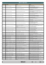
PJC 211 & 212
Alarm Descriptions
MC_0053
1. PPC520, PPC820, PPC800, PPC840
2. Buzzer is only activated when any device is sending thrust on the S-link bus.
"Err.
No."
Errors shown in display "Auto
Reset"
"Ext. buzzer
activation at
Alert Level"
Description
Action
1
Motor Overcurrent
2
(
²
)
, 3
Motor current too high.
"Thruster must be serviced by
authorized personnel, reset or power
OFF/ON PPC
(
¹
)
."
2
Motor Overtemp
Yes
2
(
²
)
, 3
"Motortemp has been over
120°C/248°F."
Motor cool down below 110°C /230°F.
3
Controller Overtemp
2
(
²
)
, 3
"PPC
(
¹
)
temp has been over
80°C/176°F."
PPC
(
¹
)
cool down below 45°C/113°F.
4
Controller Overtemp
2
(
²
)
, 3
"SR150000 temp has been over
80°C/176°F."
SR150000 cool down below 45°C
/113°F.
5
Low Voltage
2
(
²
)
, 3
Low motor voltage alarm when motor
is running.
12V thruster below 8.00V
24V thruster below 12.00V
Recharge battery, reset or power OFF/
ON device.
6
Thermoswitch
Yes
2
(
²
)
, 3
Thermo switch input is activated and
there is an open circuit.
The thruster needs to cool down before
operating again.
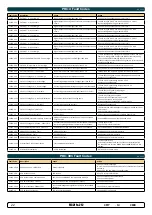
7
IPC Error
2
(
²
)
, 3
Motor relay fault
"Turn off thruster battery main switch.
Thruster must be serviced by authorized
personnel."
8
Critical Error
2
(
²
)
, 3
PPC
(
¹
)
output fail
PPC
(
¹
)
must be sent for service.
9
Low Motor Current
2
(
²
)
, 3
Thruster uses no power
Check thruster connections or motor
dead!
10
Motor Contactor
2
(
²
)
, 3
No current on motor relay coil.
Check motor relay connections, short
circuit or relay dead!
11
System Error
2
(
²
)
, 3
Fatal error
Device must be serviced by authorized
personnel
12
No Communication
2
(
²
)
, 3
No communication with device
Check S-Link cables and power
connections.
13
Motor Temp Sensor
2
(
²
)
, 3
Motor temperature sensor fail
Check for an open circuit on the temp
sensor on the motor
14
Supply Voltage Fault
2
(
²
)
, 3
No power
Check power connections
15
Fuse Blown
2
(
²
)
, 3
Fuse blown
Replace fuse or check if main cable from
battery and main cable to thruster has
been switched
16
Manual Override
Yes
2
(
²
)
, 3
Main switch manually overridden
Pull main switch
17
Motion OUT Fault
2
(
²
)
, 3
Retract obstructed while deploying
Turn off all panels. Go for lower speed/
deeper water and retry.
18
Motion IN Fault
2
(
²
)
, 3
Retract obstructed while retracting
Turn panel on and manually override
main switch. Remove obstruction and
try again.
MENU System
MC_0053
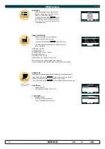
LANGUAGE
LANGUAGE
•
Choose language by moving joystick:
English, Norwegian, German, French,
Spanish, Italian and Danish.
•
Press the button below
to set
the language to the highlighted menu
entry. A star (*) on each side indicates
the language set.
DEFAULT
DEFAULT SETTINGS
•
Reset all settings to factory default
- follow instructions on screen
•
Press the button below
to confi rm reset
•
The following parameters/values will be set to the
factory settings:
Language = English
Backlight Level = 5
Backlight Night Colour = Green
Backlight Nightlevel =1
Timer Auto-Off = 05 min
Hold Calibration =70% Bow and Stern
All system devices will be erased from memory.
(Setup procedure must be followed to reconfi gure the system)
STABILIZER
STABILIZER
(Shown only for yachts equipped with a Side-Power Stabilizer system)
Press the button below
to edit the selected parameter.
ON/OFF will start to blink, use joystick to alter value.
Press the button below
to save edited parameter to device.
(Default in systems
with stabilizers)
2. AnySpeed:
•
Values: ON/OFF
•
Switches the zero speed/at
anchor stabilization ON or OFF.
1. Stabilizer:
•
Values: ON/OFF
•
Switches the stabilizer ON or OFF.


