17
2917
14
2020
-
PJC 211 & 212
The ‘HOLD’ function is for auto-run ning of bow and stern thrusters together in the direction of the arrows at selected power.
Press “+” for more and “-” for less power (6 steps). The ‘HOLD’ function is normally used to hold the boat into the dock while mooring. The ‘HOLD’
function can be deactivated by running any thruster in the opposite direction from any control unit.
The ‘HOLD’ function can be calibrated to get balanced thrust from the bow and stern thruster.
See the PJC control panel manual on how to calibrate.
HOLD Function
Calibration
Warning Signals When Using ’HOLD’ Function
MC_0053
MC_0053
MC_0053
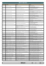
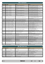
The internal and external (if fi tted) buzzer will give the following warning signals:
Warning signals
Cause
Eff ect
1.
Single short beep every 2.4 sec.
•
Voltage below 9.3V/17.5V (12V/24V system).
•
Temperature above 85oC/185oF.
None
2.
Two short beeps every 2.4 sec.
•
Voltage below 8.9V/16.3V (12V/24V system).
•
Temperature above 100oC/212oF.
None
3.
Red backlight in display and continuous short
beeps.
•
Voltage below 8.5V/15V (12V/24V system).
•
Temperature above 110oC/230oF.
None
4.
Red backlight in display and continuous short
beeps.
If one or more of the thrusters enters an alarm state
- Voltage below 8.0V/12.0V (12V/24V system) or
temperature above 120oC/248oF.
“HOLD” function are cancelled
and both thrusters will stop.
Temperature must drop below
110°C/230°F before the thruster
can be operated again. Low
Voltage alarm must be reset from
panel.
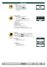
Access menu system by pressing and
holding Menu button for 3 seconds.
Move around in menus by using joystick.
Follow instructions on the screen and press the
buttons below the symbols indicated on LCD screen.
BUTTON SYMBOLS
On the bottom line of the display, a symbol will be shown over the buttons below.
These symbols will show what function each corresponding button has in the selected menu entry.
Return
to
previous menu.
Select
highlighted
menu text /
Save
edited
parameter.
Edit
highlighted
parameter.
Cancel
editing
without saving.
This symbol
indicates that the (stern)
joystick is used to move
between menu items /
parameters.
MAIN MENU ITEMS:
Move between main menu items with the (stern) joystick.
Language
Stabilizer
( If installed)
Setup
Info
Default settings
Panel setup
AC Thrusters:
Hydraulic Thrusters:
Retractable Thrusters:
DC Thrusters:
Motor temperature indicator.
Hydraulic oil temperature indicator.
Symbol shown when the thruster deploys.
Symbol shown when the thruster retracts.
Symbol shown when the thruster is in position OUT.
When the thruster is deployed and no input is given
via the joysticks/buttons over a 10 second period,
the panel will give an audible signal every 10th
second to tell that the thruster is still deployed.
Battery indicator.
From 8.5V to 12V for 12V thrusters,
15V to 24V for 24V thrusters
Motor temperature indicator.
From 70°C/ 158°F to 130°C/266°F.
Battery indicator.
From 8.5V to 12V for 12V thrusters,
15V to 24V for 24V thrusters
Motor temperature indicator.
From 70°C/ 158°F to 130°C/266°F.
Symbol shown when a DC Thruster is
used in a dual bow or dual stern setup:
Proportional Thruster Display Symbols
MC_0053
Thrust power and direction, Bow thruster(s)
Input from bow joystick on this panel.
The thrust indicator will be shown in this position on a single
joystick panel if the thruster is defi ned as a bow thruster
Extended runtime Level symbol
The ‘L’ is indicating that at least one of the BOW thrusters have it’s output
limited.
Indicating amount of thrust set by other control units in the system, i.e
additional PJC panels, 8700 Retract panel, input via 8730 S-link external
switch interface, S-link remote control etc.
If two or more units are set to run the thruster in
opposite direction, this information will not be shown.
Thrust power and direction, Stern thruster(s)
Input from stern joystick on this panel
The thrust indicator will be shown in this position on a single joystick panel if
the thruster is defi ned as a stern thruster.


