29
Installation Manual
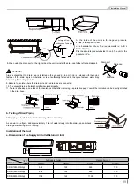
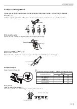
Always check that the drain cap is installed to the unused drain port and is fastened with the nylon
fastener. If the drain cap is not installed, or is not sufficiently fastened by the nylon fastener, water may
drip during the cooling operation.
8. When using the drain port on the right side of the unit, reinstall the drain cap to the left side drain port.
9. Be sure to insulate where the drain port and the drain hose is connected.
10. The unused drain port also should be insulated properly.
11. There is adhesive on one side of the insulation so that after removing the protective paper over it the insulation can be directly attached
to the drain hose.
CAUTION!
Condensate Drain pipe
Enlarged View
Condensate Drain pipe
A
A
B
B
As the inside of the unit is in the negative pressure
status, it is required to set
up a backwater elbow. The requirements is: A=B ≥
P/10+20(mm)
P is the absolute pressure inside the unit. The unit of the
pressure is Pa.
Drain port
Drain cap
Fastener
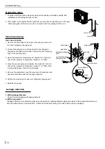
b. Testing of Drain Piping
After piping work is finished, check if drainage flows smoothly.
As shown in the figure, add approximately 1 liter of water slowly into the drain pan and check
drainage flow during COOL running.
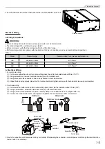
Installation of the Duct
a. Dimensions of the Supply Air Outlet/Return Air Inlet
C
A
D
B
Air Supply Outlet
Return Air Inlet
A(mm)
B(mm)
C(mm)
D(mm)
SDVH12M-A3NA(I)
538
122
590
170
SDVH18M-A3NA(I)
808
122
890
170
SDVH24M-A3NA(I)
1108
122
1190
170
Item
Model

