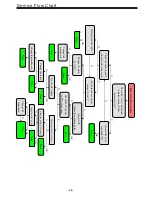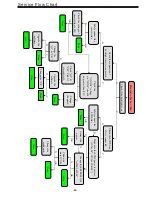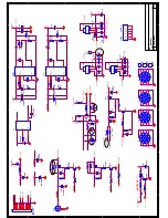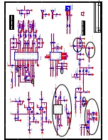
Y
Y
Y
Y
Y
Y
Y
Y
N
N
N
N
N
N
N
N
Y
Y
Y
Y
Y
Y
N
N
N
N
N
N
N
Y
N
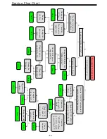
No
audio
&
No
backli
g
ht
Led
indicator
“red” on
Check
the 5V
STB on “CON8”
Press
the
“ON/OFF”
on
key
boar
d
&
re
m
o
te
control
,
led
turns
g
reen
Check
the
AC input on
p
ower
su
pp
ly
boar
d
Upgrade
the
so
ftware
Change
the
AC
line
Check
the
fuse
on
power
supply
board
Done
Change
the
fu
se
Change
the
power
supply
b
oar
d
Done
Done
Upgrade
the
software
Check
the
5V
,
12V
&
24V
on
p
ower
su
pp
ly
board
Change
the
power
supply
b
oar
d
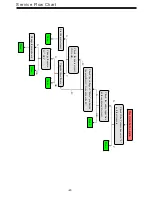
Check
the
“ON/OFF”
voltage
on
“CON8”,
sh
ould
be
greater
than
2.7V
Check
“Q3”
&
“U41” Pin81 if
it works
well.
Cha
nge
the
panel.
Done
Upgrade
the
software
Change
the
“Q
3”
or
“U9”
Change
the
“U41”
Done
Done
Done
Done
Upgrade
the
software
Done
Done
Change
the
EEPROM U43
“A
TMEL
24C64”
Done
Done
Check
all
DC
power
su
pp
ly
on
U41
Chang
the
power
su
pp
ly
IC
for
U9
Change
the
Main
IC
“U9”
Change
the
Main
b
oard
Done
Done
Done
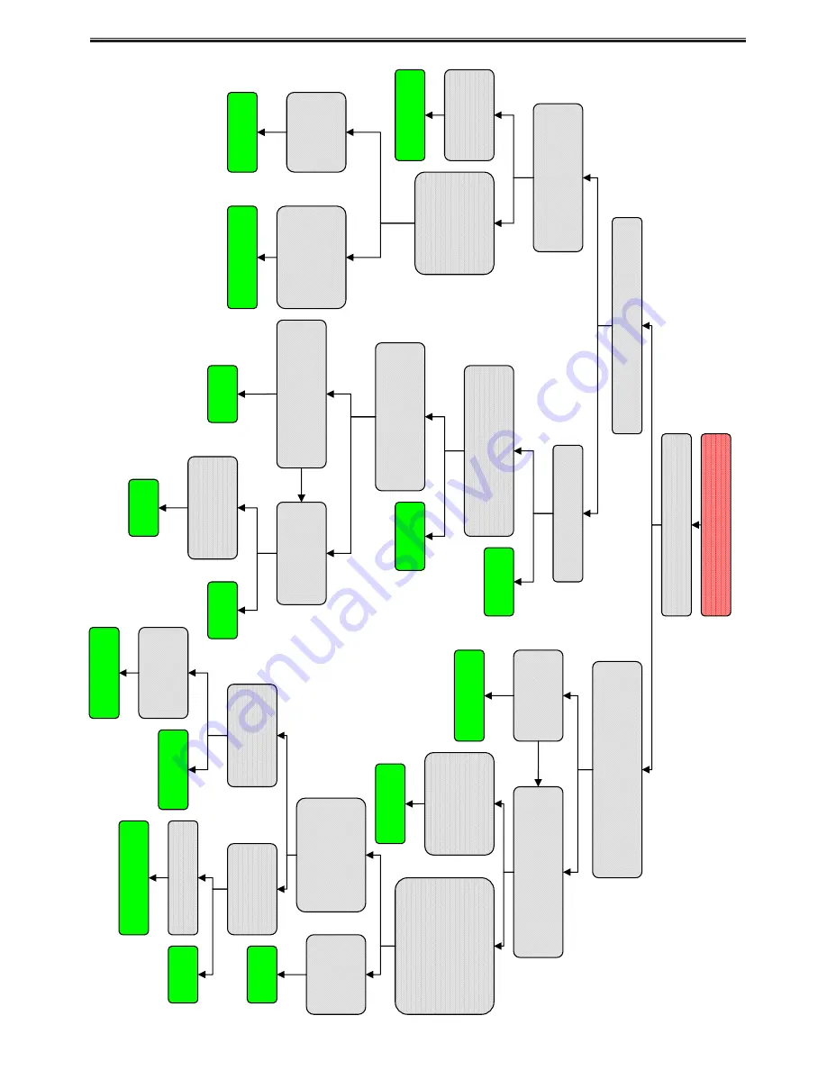
Service Flow Chart
-
4
6
-
Summary of Contents for 8M26S
Page 2: ...Content 2 11 17 18 19 20 21 28 29 45 46 49 50 57 ...
Page 3: ...LED 8M26S ...
Page 5: ...40 55 80 For 22 LED For 24 LED For 32 LED ...
Page 6: ... 24 inches is 3W 24 inches is 4 ohm ...
Page 7: ...40 40 3 2 1 4 2 50 0 5 80 40 3 12000 26inches is 8 ohm ...
Page 8: ...40 YES 8 6 46 46 NO NO Standard Spanish Standard 20 ...
Page 9: ...4 2 4 0 40 70 0 40 70 0 40 40 85 Y0 50 30000 ...
Page 14: ...IC Block Diagram 14 U29 4MX16BIT BANKS DDR M13S2561616A 5TG2K ...
Page 18: ... 18 ...
Page 19: ... 19 Main PCB Top Bottom Layer ...
Page 20: ...Main PCB Top Bottom Layer 20 ...

