EXTERNAL SCHEMATIC AND INSTALLATION
-3
0
-
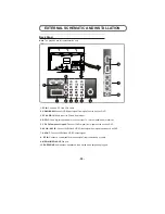
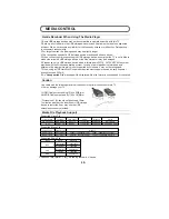
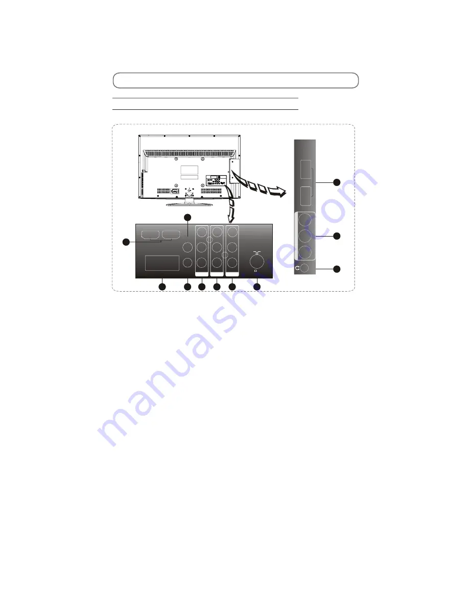
Back Panel
Note
: The graphics are for representation only.
1.PC IN:
Connect a PC via a VGA cable.
2. HDMI1\HDMI2:
Connect HDMI input signal from signal source such as DVD.
3. PC AUDIO IN:
Audio input for PC and Audio input.
4. S/PDIF:
Use a digital optical cable to connect your TV to a compatible audio receiver.
5. Y Pb Pr(Component input):
Connect YPbPr signal from signal source such as DVD.
6. AV1 IN / AV2 IN:
Connect AUDIO and VIDEO input signal from signal source such as DVD.
7. AV OUT:
Connect AUDIO and VIDEO output signal.
8. RF IN:
Connect a coaxial cable to receive signal from the antenna or cable.
9. MEDIA1\MEDIA2:
MEDIA port.
10. EARPHONE:
Audio output, speakers will be muted when earphone plugged.
HDMI1
HDMI2
PC IN
PC
AUDIO IN
S/PDIF
Y
VIDEO
VIDEO
LEFT
RIGHT
LEFT
RIGHT
AV2 IN
AV OUT
YPbPr IN
P
b
P
r
1
2
3
4
5
6
7
75
ANT
VIDEO
LEFT
RIGHT
MEDIA1
MEDIA2
AV
1
IN
8
9
6
10
Summary of Contents for 8M26S
Page 2: ...Content 2 11 17 18 19 20 21 28 29 45 46 49 50 57 ...
Page 3: ...LED 8M26S ...
Page 5: ...40 55 80 For 22 LED For 24 LED For 32 LED ...
Page 6: ... 24 inches is 3W 24 inches is 4 ohm ...
Page 7: ...40 40 3 2 1 4 2 50 0 5 80 40 3 12000 26inches is 8 ohm ...
Page 8: ...40 YES 8 6 46 46 NO NO Standard Spanish Standard 20 ...
Page 9: ...4 2 4 0 40 70 0 40 70 0 40 40 85 Y0 50 30000 ...
Page 14: ...IC Block Diagram 14 U29 4MX16BIT BANKS DDR M13S2561616A 5TG2K ...
Page 18: ... 18 ...
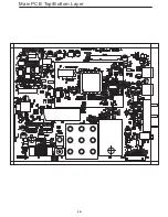
Page 19: ... 19 Main PCB Top Bottom Layer ...
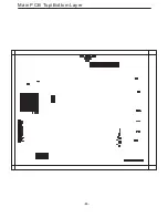
Page 20: ...Main PCB Top Bottom Layer 20 ...

