background image

DANGER

DANGER indicates an imminently hazardous situation which, if not avoided, 

will result in death or serious injury.

WARNING

WARNING indicates a potentially hazardous situation which, if not avoided, 

could result in death or serious injury.

CAUTION

CAUTION indicates a potentially hazardous situation which, if not avoided, 
may result in minor or moderate injury. It may also be used to alert against 

unsafe practices.

IMPORTANT

IMPORTANT indicates a procedure essential for safe operation and which, 

if not followed, may result in a malfunction or damage to the aerial platform.

The  Safety  Alert  Symbol  identifies  important 
safety  messages  on  aerial  platform,  safety 
signs  in  manuals  or  elsewhere.  When  you 
see  this  symbol,  be  alert  to  the  possibility  of 
personal injury or death. Follow the instructions 
in the safety message.

This Safety Alert Symbol means attention!

Become alert! Your safety is involved.

SJ 40T & SJ 45T 

SJ 61T & SJ 66T

Page 3

Summary of Contents for SJ45T

Page 1: ...TELESCOPIC BOOMS MODELS SJ40T SJ45T SJ61T SJ66T 207518AEA November 2018 OPERATING MANUAL ANSI CSA ...

Page 2: ... New South Wales 2766 Australia Tel 61 0 2 9854 0700 Fax 61 0 2 9854 0777 Skyjack Brasil Indaiatuba SP Brasil 13347 653 Tel 55 19 3936 0132 Alameda Júpiter 710 Loteamento American Park Empresarial Skyjack Service Center 3451 Swenson Ave St Charles Phone 630 262 0005 Toll Free 1 800 275 9522 Fax 630 262 0006 Email service skyjack com Illinois 60174 USA Parts Service Europe Unit 1 Maes Y Clawdd Oswe...

Page 3: ...ay also be used to alert against unsafe practices IMPORTANT IMPORTANT indicates a procedure essential for safe operation and which if not followed may result in a malfunction or damage to the aerial platform The Safety Alert Symbol identifies important safety messages on aerial platform safety signs in manuals or elsewhere When you see this symbol be alert to the possibility of personal injury or ...

Page 4: ...6 Component Identification Optional Equipment Attachments 47 3 7 Operator s Responsibility 50 3 8 Start Operation 51 3 9 Refueling Procedure 58 3 10 Loading Unloading 59 3 11 Chassis Tilt 62 Section 3 Diagrams 63 Section 4 Tables 69 Table 4 1 Standard and Optional Features 69 Table 4 2a Specifications and Features 70 Table 4 2b Specifications and Features 71 Table 4 3 Owner s Annual Inspection Rec...

Page 5: ...g replace them immediately Service Policy and Warranty SKYJACK warrants each new SJT series work platform to be free of defective parts and workmanship for the first 24 months Any defective part will be replaced or repaired by your local SKYJACK dealer at no charge for parts or labor Contact SKYJACK Service Department for warranty statement extensions or exclusions Optional Accessories The SKYJACK...

Page 6: ...r are the best insurance against an accident Therefore proper usage of this aerial platform is mandatory The following pages of this manual should be read and understood completely before operating the aerial platform Common sense dictates the use of protective clothing when working on or near machinery Use appropriate safety devices to protect your eyes ears hands feet and body Any modifications ...

Page 7: ...nergized power line up to 50 kV Energized power lines over 50 kV require a greater minimum approach distance to be maintained Refer to CFR 1910 333 As per CSA B354 4 02 The operator shall maintain the minimum safe approach distance MSAD from energized conductors at all times in accordance with the authority having jurisdiction Refer to CFR 1910 333 or the authority having jurisdiction DO NOT USE A...

Page 8: ...uipment DO NOT raise the platform in windy or gusty conditions DO NOT increase the lateral surface area of the platform Increasing the area exposed to the wind will decrease aerial platform stability Avoid tenting DO NOT elevate the aerial platform if it is not on a firm level surface DO NOT drive elevated near depressions or holes of any type loading docks debris drop offs and surfaces that may a...

Page 9: ...g hazards when lifting or driving Keep all body parts inside the aerial platform BE AWARE of blind spots when operating the aerial platform ENSURE that there are no personnel or obstructions in the path of travel including blind spots DO NOT lower the platform unless the area below is clear of personnel and obstructions DO NOT use boom to push pull other objects or to lift the chassis DO NOT raise...

Page 10: ...ols until personnel are removed from the platform DO NOT position the aerial platform against another object to steady the platform DO NOT place materials on the guardrails or materials that exceed the confines of the guardrails unless approved by Skyjack DO NOT operate if aerial platform is not working properly or if any parts are damaged or worn DO NOT leave aerial platform unattended with key i...

Page 11: ...cted and used in accordance with the manufacturer s recommendations All personal fall protection equipment must be attached only to approved anchorage points within the platform of the aerial platform WARNING Entering and exiting the aerial platform should only be done using the three points of contact Use only equipped access openings Enter and exit only when the aerial platform is in the fully r...

Page 12: ...Page 12 SJ 40T SJ 45T SJ 61T SJ 66T Notes ...

Page 13: ...perate an aerial platform Do not operate this aerial platform without proper authorization and training Failure to avoid this hazard could result in death or serious injury It is the responsibility of the operator to read completely understand and follow all instructions and warnings contained in this operating manual and on the aerial platform Footswitch Platform Control Console Base Control Cons...

Page 14: ...d or unloaded from a trailer using a winch line 2 2 2 Main Power Disconnect Switch This switch is located in the engine compartment near the battery 1 Figure 2 2 Main Power Disconnect Switch 1 Main Power Disconnect Switch This switch when in off position disconnects power to all circuits Switch must be in on position to operate any circuit Turn switch off when transporting aerial platform 2 2 3 Br...

Page 15: ... Lock Switch This switch is located on the platform control console The differential locking system provides more traction by providing equal drive to each wheel regardless of traction Differential locks are used to prevent from getting stuck when driving on loose muddy or rocky terrain Refer to Section 2 4 3 for instruction regarding testing differential lock switch WARNING Before engaging differ...

Page 16: ...cy power unit position allows base control functions to operate using emergency power unit b Start Emergency Power Switch This switch starts engine or enables emergency power unit c Function Enable Switch When held in either direction this momentary switch allows base control functions to operate 4a Off Base Platform Key Switch This three way selector switch allows operator to turn off power to ae...

Page 17: ... back in to reset 13a Status Indicator Pilot Lights These lights indicate operational status and errors in any function in the controls engine A B C D E F A Water In Fuel Light This light indicates water separator is full Open drain to release water Engine damage could occur if ignored for excessive length of time B Engine Oil Pressure This light indicates low engine oil pressure C Engine Coolant ...

Page 18: ...is light indicates overheating of engine coolant D Engine This light indicates failure in engine control system E Fuel This light indicates low fuel level F Glow Plug Diesel This light illuminates until glow plugs have completed their timed cycle When the lamp goes out the engine is ready to be started 14 Positive Air Shutoff Switch If Equipped This switch allows the operator to shut off the air s...

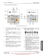
Page 19: ...s when footswitch is depressed A 15 second anti tiedown feature deactivates footswitch when operator depresses it for 15 seconds without activating any function B Chassis Tilt This light illuminates when the aerial platform chassis is at an inclination that activates the tilt sensor At this inclination an audible alarm will sound at the platform Refer to Section 3 11 for instructions regarding rec...

Page 20: ...ward and then released disengages differential lock and turns differential light off 11 Jib Up Down Switch This switch controls up or down movement of jib 12 Function Speed Adjuster Dial This variable speed adjuster controls speed of fly boom extension retraction jib raising lowering and platform rotation movements This is used with switches 10 12 and 14 13 Fly Boom Extend Retract Switch This swit...

Page 21: ...taining the electrical components is essential to good performance and service life of the aerial platform Inspect the following areas for chafed corroded and loose wires boom to platform cable harness engine compartment electrical panel engine wiring harness rotary manifold wiring 2 3 3 Limit Switches Ensure limit switches are properly secured with no signs of visible damage and movement is not o...

Page 22: ... protection as well as appropriate protective clothing If contact occurs immediately flush with cold water and seek medical attention 1 Check battery case for damage 2 Clean battery terminals and cable ends thoroughly with a terminal cleaning tool or wire brush 3 Ensure all battery connections are tight 4 If applicable check battery fluid level If plates are not covered by at least 1 2 13 mm of so...

Page 23: ...ssing parts and no visible damage to the engine pivot tray Ensure that each tray securing bolt is in place Engine Oil Level Maintaining the engine components is essential to good performance and service life of the aerial platform WARNING Beware of hot engine components Check oil level on dipstick Oil level should be in the safe zone Add oil as needed Refer to Table 4 2b for recommended oil type E...

Page 24: ...s needed Refer to Table 4 2b for recommended oil type Hydraulic Return Filter Ensure filter element is secure Ensure there are no signs of leakage or visible damage Brake and Main Manifolds Ensure all fittings and hoses are properly tightened and there is no evidence of hydraulic leakage Ensure there are no loose wires or missing fasteners Emergency Power Unit Ensure there are no loose or missing ...

Page 25: ... cylinder assembly is properly secured there are no loose or missing parts all fittings and hoses are properly tightened and there is no evidence of hydraulic leakage NOTE Oscillating axle is locked when aerial platform is in low speed Refer to Diagram 3 5 Axle Oscillation Diagrams Steer Cylinder Assembly Ensure steer cylinder assembly is properly secured there are no loose or missing parts all fi...

Page 26: ...d type Failure to operate with matched approved tires in good condition may result in death or serious injury 2 3 8 Manuals Ensure a copy of operating manual and other important documents are enclosed in manual storage box Check to be sure manual storage box is present and in good condition Ensure manuals are legible and in good condition Always return manuals to the manual storage box after use 2...

Page 27: ...acks in welds or structure and there are no signs of deformation Ensure all hoses are properly tightened and there is no evidence of hydraulic leakage Cylinders Ensure all cylinders are properly secured and there is no evidence of leakage Wear Pads Ensure all bolts are tight there is no visible damage to the wear pads and that no parts are missing Hoses Ensure all hoses are properly tightened and ...

Page 28: ...o loose or missing parts and there is no visible damage Ensure there are no loose wires or missing fasteners Work Light If Equipped Ensure lamps are properly secured with no signs of visible damage Ensure mounting bracket is properly secured Ensure there are no loose wires or missing fasteners Flashing Amber Light If Equipped Ensure lamp is properly secured with no signs of visible damage Glazier ...

Page 29: ...operating any boom and drive function 2 4 1 Test Main Power Disconnect Switch 1 In engine compartment turn main power disconnect switch to off position Result Aerial platform functions should not operate 2 In engine compartment turn main power disconnect switch to on position NOTE Close all cowlings before proceeding to next item 2 4 2 Base Control Console 1 On platform control console pull out em...

Page 30: ...ll boom and platform functions should not operate 4 Hold start function enable emergency power function enable switch in function enable position and activate each boom and platform function Result Engine speed increases from idle to intermediate All boom and platform functions should operate as selected Test Platform Self leveling 1 Lower boom to stowed position 2 Adjust platform to a level posit...

Page 31: ...se control console pull out emergency stop button 4 Select emergency power position from start function enable emergency power start emergency power switch and activate each boom function Result All selected functions should operate NOTE The emergency power unit has two minute duty cycle Test Off Base Platform Base Off Platform Switch 1 Ensure emergency stop button is pulled out 2 Start engine 3 O...

Page 32: ...ntrol console attempt to activate each boom and platform switch while holding start function enable emergency power function enable switch in function enable position Result All boom and platform functions should not operate while holding start function enable emergency power function enable switch in function enable position 10 Push in emergency stop button to turn engine off 11 Pull out emergenc...

Page 33: ... push rocker switch to on position 3 Push rocker switch to off position LED light should continuously illuminate Walk back to the engine compartment side of the aerial platform Result The shutoff valve should disengage after 20 seconds refer to shutoff valve diagrams 4 Close engine compartment cover Ensure switch is returned to off position and switch guard is down Base Control Console Shutoff Val...

Page 34: ...rgency stop button 2 Ensure engine start on off switch is in on position 3 Do not start engine 4 Select generator on off switch to off position if equipped 5 Depress and hold footswitch and attempt to start engine by selecting start position from engine start on off switch Result Engine should not start 6 Without depressing footswitch try to start engine Result Engine should start 7 With engine ru...

Page 35: ...ould not operate Test Steering 1 Pull out emergency stop button 2 Start engine by selecting start position from engine start on off switch 3 Depress and hold footswitch 4 Press rocker switch on top of drive steer controller to left and right Result Steer wheels should turn left and right Test Driving Function 1 Ensure path of intended motion is clear 2 Ensure boom is in stowed position and fly boo...

Page 36: ...ry power do not operate more than one function at a time to avoid overloading 12 Volt auxiliary pump motor Do not use emergency power unit continuously for two minutes NOTE To conserve battery power test each function through a partial cycle 1 On platform control console push in emergency stop button to turn engine off 2 Pull out emergency stop button 3 Select on position from engine start on off ...

Page 37: ...adjustments have been checked Test Manual Platform Leveling 1 Depress and hold footswitch 2 On platform leveling override switch select up position to tilt platform up or down position to tilt platform down Result Platform should tilt up or down Test Differential Lock Switch WARNING Before engaging differential lock ensure drive steer controller is in neutral position 1 On platform control console...

Page 38: ...ile on a firm level ground Result The steer axles should be locked 2 Drive one of the steer tires up onto a 6 in 15 cm block or curb Result An appropriate tilt of the aerial platform chassis should occur 3 Retract fly boom while in tilt position Result The steer axles should unlock and the aerial platform chassis should level itself to ground Test Cables 61T 66T 1 Raise the main boom to approximat...

Page 39: ... a speed of 2 in sec 50 mm sec WARNING When pushing winching or towing do not exceed 2 mph 3 2 km h WARNING Do not winch or tow aerial platform on grade steeper than 50 2WD 4WD WARNING Do not winch or tow aerial platform onto a slope or brake the towing vehicle rapidly Do not pull aerial platform down an incline towards a winch 1 Before winching or towing aerial platform fully retract lower and po...

Page 40: ...pass the drive pump by loosening the valve stem item 1 marked with yellow paint two revolutions counterclockwise 1 Figure 2 8 Drive Bypass Valve CAUTION Do not release brakes before disengaging drive motor 4 Push in black brake valve plunger item 3 1 3 2 Figure 2 9a Brake Manifold SJ40 45T 3 1 2 Figure 2 9b Brake Manifold SJ61 66T 5 Actuate red hand pump item 1 slowly by moving knob in and out unt...

Page 41: ...o not use emergency power unit continuously for more than two minutes 2 6 1 Base Control Console 1 Ensure engine is off 2 Pull out emergency stop button 3 Turn key switch to base position 4 Select emergency power position from start function enable emergency power start emergency power switch and activate desired boom function 2 6 2 Platform Control Console 1 Ensure engine is off 2 Pull out emerge...

Page 42: ...Page 42 SJ 40T SJ 45T SJ 61T SJ 66T Notes ...

Page 43: ...ntenance WARNING Maintenance must be performed by trained and competent personnel who are familiar with mechanical procedures Death or serious injury could result from the use of an aerial platform that is not properly maintained or kept in good working condition The operator must be sure that the aerial platform has been properly maintained and inspected before using it The operator must perform ...

Page 44: ... Major Components SKYJACK Telescopic Boom Platform Jib Control Compartment Engine Compartment Base Fly Boom Turret Main Boom Power Track Platform Control Console Base Control Console Lift Cylinder Mid Boom Page 44 SJ 40T SJ 45T SJ 61T SJ 66T ...

Page 45: ...y Model 66T has an additional mid boom section The telescoping boom mechanism uses two double acting hydraulic cylinders with holding valves to control vertical movement Cables are used to extend the fly boom section in the 66T model SJ 45T SJ 66T models are equipped with a 60 in 150 cm boom jib controlled by a double acting hydraulic cylinder 3 3 4 Platform The platform is constructed of a skid r...

Page 46: ...ed to hold transportation lock in either locked or unlocked position Refer to Section 3 10 2 for procedure on how to lock the turret 3 5 2 All Motion Alarm This alarm produces an audible sound when any boom function is activated On aerial platforms with certain op tions a flashing amber light will accompany this alarm 3 5 3 Manual Storage Box This weather resistant box is mounted under the control...

Page 47: ...that valve stem is at the top to prevent sealant from entering the stem refer to Figure 3 2 If tire no longer holds pressure replace tire WARNING The sealant contains propylene glycol Do not ingest inhale or get into eyes If it gets into your eyes flush with water for 15 minutes Consult physician 3 6 2 AC Outlet on Platform If Equipped This outlet is a source of AC power on the platform The outlet...

Page 48: ...Work Light This light turns on when plugged into the AC outlet on the platform WARNING Work lights are not intended to replace the ambient lighting required to navigate and operate this aerial platform 3 6 6 Glazier Tray If Equipped The tray is installed on the front side of the platform 3 1 2 Figure 3 7 Glazier Tray 1 Strap This strap is used to secure panel in place 2 Foam Support This foam supp...

Page 49: ...OTE This option adds 90 lb 41 kg to the platform This weight must be included when determining the total load on the platform including personnel and other materials WARNING Only qualified persons should install operate maintain and repair the welder CAUTION Breathing welding fumes and gases can be hazardous to your health 3 6 8 Arctic Weather Package If Equipped The heater plug is located on the ...

Page 50: ...rstand and follow the step by step instructions to test all aerial platform functions The operator should make a copy of the Operator s Checklist see Table 4 8 and fill out the visual and daily maintenance inspections and the function tests sections while performing the items outlined in Section 2 3 and Section 2 4 IMPORTANT If aerial platform is damaged or any unauthorized variation from factory ...

Page 51: ... to be working properly has been damaged or appears to have worn or missing parts has alterations or modifications not approved by the manufacturer has safety devices which have been altered or disabled has been tagged or locked out for non use or repair Failure to avoid these hazards could result in death or serious injury 3 8 1 To Activate Base Control Console WARNING Ensure that you maintain th...

Page 52: ...g and holding start function enable emergency power function enable switch to function enable position 2 Push jib up down switch to either up or down position Release switch to stop 3 8 5 To Raise or Lower Main Boom Using Base Control Console 1 Activate function enable by selecting and holding start function enable emergency power function enable switch to function enable position 2 Push main boom...

Page 53: ...m WARNING DO NOToperate any control on operator s control console without proper fall protection secured to the designated location in the platform Failure to avoid this hazard could result in death or serious injury 4 Enter platform and close gate 5 Attach body harness lanyards of each occupant to platform lanyard rings 6 On platform control console pull out emergency stop button 7 Select start p...

Page 54: ...ess and hold footswitch 2 Press rocker on top of drive steer controller in this direction to steer left or to steer right NOTE Driving and steering may be active at the same time 3 8 12 To Move Jib Up and Down Using Platform Control Console If Equipped 1 Depress and hold footswitch 2 On jib up down switch select to move jib up or to move jib down Vary speed with boom speed adjuster dial Release sw...

Page 55: ...ergency power unit has two minute duty cycle CAUTION Do not use emergency power unit continuously for two minutes 3 8 20a To Engage Differential Lock Switch 1 Depress and hold footswitch 2 On platform control console push differential lock switch forward to the locked position and then release 3 8 20b To Disengage Differential Lock Switch 1 Ensure path of intended motion is clear 2 Depress and hol...

Page 56: ...latform control console turn generator on off switch to off position NOTE An engine shut down will turn the generator off Normal boom functions are disabled while the generator is on 3 8 23 Glazier Tray If Equipped 1 Ensure that boom is retracted and platform fully lowered 2 Place panel on tray and center it to make sure weight is evenly balanced on the platform 3 Secure panel in place using the s...

Page 57: ...mpts consult Troubleshooting Information in the Service and Maintenance Manual IMPORTANT Ensure heater is unplugged before operating aerial platform NOTE Ifaerialplatformistobeparkedforanextendedperiod oftime removethebatteryandstoreitinawarmplace Refer to the cold weather operation chart Figure 3 11 to assist in operating the aerial platform in cold weather conditions 1 Hydraulic Tank Turret Figu...

Page 58: ...oline engine models Use only unleaded gasoline with an octane rating 87 or higher WARNING Do not smoke in an area where aerial platforms are stored or refueled CAUTION When operating on a slope ensure fuel level is above half to avoid a possible stall condition IMPORTANT Before using your aerial platform ensure there is enough fuel for expected use 3 9 1 Regular Fuel Gasoline or Diesel IMPORTANT U...

Page 59: ...oaded or unloaded 3 10 1 Loading and Tie down 1 Lock turret using turret transportation lock refer to Section 3 10 2 2 Turn key switch to off position and remove key before transporting 3 Turn main power disconnect switch to off position 4 Chock aerial platform wheels if necessary 5 Remove all loose items 6 Anchor down aerial platform to transport surface using tie down points refer to Figure 3 12...

Page 60: ...ft points only refer to Figure 3 13 2 Turn main power disconnect switch to off position 3 Clear platform of all personnel tools and materials WARNING When lifting the aerial platform lifting devices must be attached to designated lift points only refer to Figure 3 14 WARNING Use chains with load capacity sufficient to withstand aerial platform weight Refer to the serial plate of the aerial platfor...

Page 61: ...ed lift points only refer to Figure 3 16 and Figure 3 17 WARNING Use chains with load capacity sufficient to withstand aerial platform weight Refer to the serial plate of the aerial platform for specific weight 4 Properly adjust rigging to ensure aerial platform remains level during lifting See Center of gravity location Figure 3 15 Figure 3 17 61 66T Lifting Points Figure 3 16 61 66T Overhead Vie...

Page 62: ...terweight Uphill Iftheaerialplatformbecomestiltedwiththecounterweight uphill refer to Figure 3 18 follow the steps below to return to a lowered and retracted position 1 Retract the fly boom completely 2 Drive to a firm level surface 3 11 2 Counterweight Downhill Iftheaerialplatformbecomestiltedwiththecounterweight downhill refer to Figure 3 19 follow the steps below to return to a lowered and retr...

Page 63: ... 10 25 7 62 30 9 14 35 10 67 40 12 19 Feet meters 10 3 05 5 1 52 0 5 1 52 10 3 05 15 4 57 20 6 10 25 7 62 30 9 14 35 10 67 35 10 67 40 12 19 45 13 72 50 15 24 Figure 3 20 Reach Diagram 40T 2 08 m 10 36 m 0 94 m 12 37 m 2 27 m 0 91 m 2 44 m 2 39 m 0 86 m 2 44 m Figure 3 21 Dimension 40T SJ 40T SJ 45T SJ 61T SJ 66T Page 63 ...

Page 64: ... 62 30 9 14 35 10 67 40 12 19 Feet meters 10 3 05 5 1 52 0 5 1 52 10 3 05 15 4 57 20 6 10 25 7 62 30 9 14 35 10 67 35 10 67 40 12 19 45 13 72 50 15 24 Figure 3 22 Reach Diagram 45T 13 77 m 2 08 m 12 12 m 0 94 m 2 27 m 0 91 m 2 44 m 1 52 m 2 39 m 0 86 m 2 44 m 8 79 m Figure 3 23 Dimensions 45T Page 64 SJ 40T SJ 45T SJ 61T SJ 66T ...

Page 65: ...9 14 25 7 62 20 6 10 15 4 57 10 3 05 5 1 52 10 3 05 Feet meters 65 19 81 60 18 29 55 16 76 50 15 24 45 13 72 40 12 19 35 10 67 30 9 14 25 7 62 20 6 10 15 4 57 10 3 05 5 1 52 5 1 52 10 3 05 Figure 3 24 Reach Diagram 61T 2 41 m 15 63 m 18 67 m 1 20 m 2 43 m 2 43 m 0 92 m 2 56 m 9 24 m 2 44 m 1 18 m Figure 3 25 Dimension 61T SJ 40T SJ 45T SJ 61T SJ 66T Page 65 ...

Page 66: ... 14 25 7 62 20 6 10 15 4 57 10 3 05 5 1 52 10 3 05 Feet meters 65 19 81 60 18 29 55 16 76 50 15 24 45 13 72 40 12 19 35 10 67 30 9 14 25 7 62 20 6 10 15 4 57 10 3 05 5 1 52 5 1 52 10 3 05 Figure 3 26 Reach Diagram 66T 17 37 m 1 20 m 2 43 m 2 43 m 0 92 m 2 56 m 1 18 m 10 34 m 2 44 m 2 41 m 20 12 m Figure 3 27 Dimensions 66T Page 66 SJ 40T SJ 45T SJ 61T SJ 66T ...

Page 67: ...n free travel mode drive speed 4 5 mph 7 2 km h max Axle oscillation locked work mode drive speed 0 5 mph 0 8 km h max Figure 3 28 Axle Oscillation SJ 40T 61T Axle oscillation free travel mode drive speed 4 5 mph 7 2 km h max Axle oscillation locked work mode drive speed 0 5 mph 0 8 km h max Figure 3 29 Axle Oscillation SJ 45T 66T SJ 40T SJ 45T SJ 61T SJ 66T Page 67 ...

Page 68: ...Page 68 SJ 40T SJ 45T SJ 61T SJ 66T Notes ...

Page 69: ... P P P 5 foot jib Not Applicable Not Applicable GM 3 0L dual fuel engine gas propane P P P Two wheel drive P P P Welder package with 12kW hydraulic generator 3500W hydraulic generator Cold weather start kit diesel or dual fuel P P P Flashing amber light P P P Platform work light P P P Base driving light Not Available Not Available Glazier package P P P Air line or hydraulic line to platform P P P ...

Page 70: ...in 5 0 m 16 ft 7 in 5 0 m 4WD 18 ft 7 in 5 7 m 18 ft 7 in 5 7 m 16 ft 7 in 5 0 m 16 ft 7 in 5 0 m 60629AE ANSI Platform rotate full 5 9 seconds approx 5 9 seconds approx Driving Speeds Drive Speed maximum stowed 4 5 mph 7 2 km h 4 5 mph 7 2 km h Drive Speed maximum elevated 0 5 mph 0 8 km h 0 5 mph 0 8 km h Jib down 10 16 seconds approx 10 16 seconds approx Turret rotate counterclockwise 360 fully...

Page 71: ...city 59 gal 223 3 L Hydraulic Oil Hyd Cooler Option Ambient Temperature Limits Oil cooler option recommended Standard Factory Fill Shell Tellus T46 Arctic Oil Option Coolant Capacity 3 17 gal 12 L Mobilfluid 424 Esso UNIVIS N46 Chevron Rycon MV Mobil DTE 13M Esso UNIVIS N22 Petro Canada HYDREX MV Arctic 15 Esso Mobil UNIVIS HVI 26 Petro Canada HYDREX EXTREME Approved Alternates Standard Oil Factor...

Page 72: ..._ Serial Number __________________ 20__ 20__ 20__ 20__ 20__ 20__ Pictorial Description Inspection Date Inspector Signature Table 4 4 Maximum Platform Capacities SJ 40T SJ 45T SJ 61T SJ 66T 650 lb 295 kg 500 lb 227 kg 500 lb 227 kg 500 lb 227 kg 2 Persons 2 Persons 2 Persons 2 Persons Maximum Wind 28 mph 12 5 m s 28 mph 12 5 m s 28 mph 12 5 m s 28 mph 12 5 m s Maximum Side Force 90 lbf 400 N 90 lbf...

Page 73: ...93 2 Nm 290 ft lb 393 2 Nm 60565AD ANSI WARNING Intermixing tires of different types or using tires of types other than those originally supplied with this equipment can adversely affect stability Therefore replace tires only with the exact Skyjack approved type Failure to operate with matched approved tires in good condition may result in death or serious injury SJ 40T SJ 45T SJ 61T SJ 66T Page 7...

Page 74: ...he area in direct contact with the floor The floor covering tile carpet etc must be able to withstand more than the indicated values above Total Aerial Platform Load Wheel LCP OUP OUP Overall Uniform Pressure is a measure of the average load the aerial platform imparts on the whole surface projected directly underneath it The structure of the operating surface beams etc must be able to withstand m...

Page 75: ...n Enable Switch All Boom Functions A Hydraulic Oil A Test Platform Self leveling A Hydraulic Return Filter A Test Emergency Power A Brake and Main Manifolds A Test Base Off Platform Switch A Emergency Power Unit A Test Positive Air Shutoff If Equipped A Fuel Tank A Platform Control Console Fuel Leaks A Test Footswitch A Base Test Emergency Stop A Turret Transportation Lock A Test Steering A Drive ...

Page 76: ... Console Test Emergency Stop Muffler and Exhaust Flashing Amber Light If Equipped Engine Pivot Tray Glazier Tray If Equipped Engine Oil Level Arctic Weather Package If Equipped Rotary Manifold Battery Warmer Hydraulic Oil Heater If Equipped High Pressure Filter 40T 45T Welder If Equipped Hydraulic Pumps Work Light If Equipped Swing Drive Motor Optional Equipment Attachments Turret Rotation Gear Hy...

Page 77: ...R Safety Orange Safety Orange indicates WARNING Safety Yellow Safety Yellow indicates CAUTION Safety Green Safety Green indicates emergency lowering Safety Blue Safety Blue indicates safety information SJ 40T SJ 45T SJ 61T SJ 66T Page 77 Section 5 Labels ...

Page 78: ...ng Do Not Alter Do not alter or disable limit switches or other safety devices 3 Model Number Product Identifier Model number will vary may not be as shown 4 Skyjack Logo Skyjack Engine Side 139314AA 39314AA 139314AA 1 3 4 3 2 4 Page 78 SJ 40T SJ 45T SJ 61T SJ 66T Labels Section 5 ...

Page 79: ...r Body crushing hazard 7 Lift and Tie Down Points Only use these points for lifting or tying down 8 Wheel Load Indicates rated wheel load Wheel load will vary over different aerial platforms Engine Side Continued 139314AA 39314AA 139314AA 8 6 5 7 8 6 7 6 6 SJ 40T SJ 45T SJ 61T SJ 66T Page 79 Section 5 Labels ...

Page 80: ... tires 10 Tire Pressure Indicates rated tire pressure Foam filled Tire If Equipped Indicates foam filled tire 11 Wheel Specifications Refer to manual for wheel type offset pressure and torque Engine Side Continued 139314AA 139314AA 139314AA 9 10 11 9 11 10 Page 80 SJ 40T SJ 45T SJ 61T SJ 66T Labels Section 5 ...

Page 81: ...brake valve and pump 6 Push in black knob 7 Pump by slowly pushing red knob in and out until 300 psi 21 bar shows on the gauge if equipped Brake is now released Refer to Section 2 5 Winching Towing Procedure 8 A Remove blocks from wheels B Push tow winch to desired location 9 Block or chock wheels to prevent aerial platform from rolling At hydraulic tank side 10 Reset brake by pulling out black kn...

Page 82: ...ng Do Not Alter Do not alter or disable limit switches or other safety devices 4 Cold Weather Factory Oil If Equipped Recommended factory oil 5W 30 for cold weather start option 5 Battery Warmer Hydraulic Oil Heater If Equipped Battery warmer hydraulic oil heater cord Page 82 SJ 40T SJ 45T SJ 61T SJ 66T Labels Section 5 ...

Page 83: ...escription 1 Serial Plate Product identification and specifications Serial plate will vary may not be as shown 2 4x4 If Equipped Product Identifier 4 wheel drive Front Side SJ 40T SJ 45T SJ 61T SJ 66T Page 83 Section 5 Labels ...

Page 84: ...Skyjack 3 Diesel Ultra Low Sulfur Only Diesel Ultra Low Sulfur Only Diesel Use diesel fuel only Unleaded Fuel Use unleaded gasoline only 4 No Smoking Do not smoke near this location Control Side 2 3 1 4 2 ZZ 139314AA ZZ Clearance Requirements Page 84 SJ 40T SJ 45T SJ 61T SJ 66T Labels Section 5 ...

Page 85: ... fuel tank 6 Model Number Product Identifier Model number will vary may not be as shown 7 Body Crushing Hazard Danger Body crushing hazard 8 Crushing Hazard Danger Crushing hazard 9 Lift and Tie Down Points Only use these points for lifting or tying down ZZ 139314AA ZZ Clearance Requirements 6 7 8 7 7 9 9 5 SJ 40T SJ 45T SJ 61T SJ 66T Page 85 Section 5 Labels ...

Page 86: ...load will vary over different aerial platforms 12 Tire Pressure Indicates rated tire pressure Foam filled Tire If Equipped Indicates foam filled tire 13 Wheel Specifications Refer to manual for wheel type offset pressure and torque Control Side Continued 10 11 12 13 10 12 11 13 ZZ 139314AA Clearance Requirements Page 86 SJ 40T SJ 45T SJ 61T SJ 66T Labels Section 5 ...

Page 87: ...m has received annual inspection prior to operation 15 Emergency Lowering Procedure In case of emergency follow procedure outlined in label to lower the platform Control Side Continued 15 14 139314AA ZZ Clearance Requirements SJ 40T SJ 45T SJ 61T SJ 66T Page 87 Section 5 Labels ...

Page 88: ...ch shift Refer to Table 4 7 Maintenance and Inspection Schedule 4 kg lb Platform Capacity Rated work load in each configuration Rated work load includes the weight of both personnel and material and maximum number of people in each configuration Do not exceed total weight or maximum number of people Load platform uniformly Platform capacity will vary over different aerial platforms Platform Views ...

Page 89: ...e left or to rotate to the right Select to tilt platform up or to tilt platform down Select to move jib up or to move jib down Select to rotate turret to the left or to rotate to the right Select to raise main boom or to lower main boom Select to extend fly boom or to retract fly boom Select to turn engine off to enable base control console or to enable platform control console Push emergency stop...

Page 90: ...atform up or to tilt platform down Select to move jib up or to move jib down Push and hold in either direction to enable base control functions Select to rotate turret to the left or to rotate to the right Select to raise main boom or to lower main boom Select to extend fly boom or to retract fly boom Select to enable base control console to turn engine off or to enable platform control console Pu...

Page 91: ...roved alternate see Table 4 2b Note Cold weather starting temperatures can be improved with Skyjack options Please consult your nearest Skyjack service center 4 Hydraulic Oil Level Indicates minimum maximum oil level 5 Positive Air Shutoff If Equipped Use this switch to trigger the positive air shutoff valve Control Compartment Continued 3 2 4 5 SJ 40T SJ 45T SJ 61T SJ 66T Page 91 Section 5 Labels...

Page 92: ...black knob 7 Pump by slowly pushing red knob in and out until 300 psi 21 bar shows on the gauge if equipped Brake is now released Refer to Section 2 5 Winching Towing Procedure 8 A Remove blocks from wheels B Push tow winch to desired location 9 Block or chock wheels to prevent aerial platform from rolling At hydraulic tank side 10 Reset brake by pulling out black knob At engine side 11 Close bypa...

Page 93: ...r Only Diesel Ultra Low Sulfur Only Diesel Use diesel fuel only Unleaded Fuel Use unleaded gasoline only 9 No Smoking Do not smoke near this location 10 Connect AC Supply Connect AC supply here 11 Glow Plug Procedure When glow plug diesel light is on wait and do not start engine Control Compartment Continued 8 9 10 11 7 SJ 40T SJ 45T SJ 61T SJ 66T Page 93 Section 5 Labels ...

Page 94: ...No Label Pictorial Description 1 No Smoking Do not smoke near this location 2 PROPANE Propane Indicates propane storage location Propane 1 2 1 2 Page 94 SJ 40T SJ 45T SJ 61T SJ 66T Labels Section 5 ...

Page 95: ...Operate below indicated wind speed only 4 kg lb Platform Capacity Rated work load in each configuration Rated work load includes the weight of both personnel and material and maximum number of people in each configuration Do not exceed total weight or maximum number of people Load platform uniformly Platform capacity will vary over different aerial platforms Rear Side 1 2 3 1 2 4 SJ 40T SJ 45T SJ ...

Page 96: ... Identification Refer to Section 1 Safety Rules Read and understand outlined risks associated with this work platform prior to operation 7 Model Number Product Identifier Model number will vary may not be as shown Rear Side Continued 7 5 6 Page 96 SJ 40T SJ 45T SJ 61T SJ 66T Labels Section 5 ...

Page 97: ...icates full body harness awareness 10 Skyjack Logo Skyjack 11 Cancer and Reproductive Harm https www p65warnings ca gov WARNING Warning California Proposition 65 Cancer and Reproductive Harm https www p65warnings ca gov Rear Side Continued 10 8 11 9 SJ 40T SJ 45T SJ 61T SJ 66T Page 97 Section 5 Labels ...

Page 98: ...ned in label to lower the platform 3 E Stop Horn Select to sound horn Read operating manual Push emergency stop to stop engine and disable controls 4 Engine Controls Emergency Power Unit Select to enable emergency power unit Select low torque higher speed or high torque lower speed Select high torque when driving on a slope Select either high or low engine throttle speed Select to engage different...

Page 99: ...ion to raise main boom or to lower main boom 7 Boom Jib Platform Controls Select to rotate platform to the left or to the right Select to tilt platform up or to tilt platform down Select to extend fly boom or to retract fly boom Select to move jib up or to move jib down 8 Drive Steer Controller Push and hold controller in this direction to drive forward or to drive backward Push and hold controlle...

Page 100: ...anger Crushing hazard 3 Connect AC Supply Connect AC supply here 4 Warning Do Not Alter Do not alter or disable limit switches or other safety devices 5 Footswitch Enable On Off Depress and hold footswitch to enable platform function Platform Railing Page 100 SJ 40T SJ 45T SJ 61T SJ 66T Labels Section 5 ...

Page 101: ...ial Description 1 Warning Hazardous Voltage Electric shock warning 2 Catalytic Muffler Lower Emissions Indicates lower emissions Optional Equipment Attachments 1 2 SJ 40T SJ 45T SJ 61T SJ 66T Page 101 Section 5 Labels ...

Page 102: ...iption 3 kg lb Welder Weight Indicates rated weight of welder 4 Glazier Tray Capacity Indicates rated capacity of glazier tray Optional Equipment Attachments Continued 3 4 Page 102 SJ 40T SJ 45T SJ 61T SJ 66T Labels Section 5 ...

Page 103: ... Terrain Scissor Lifts Boom Lifts and Telehandlers in the most challenging of conditions A unique boom feature only utilized by Skyjack the Boom Lift drive function operates in accordance with the general orientation of the turret s counterweight over the chassis i e joystick forward counterweight facing forward This provides intuitive operation by allowing the unit to move in the general directio...

Page 104: ...Page 104 SJ 40T SJ 45T SJ 61T SJ 66T Notes ...

Page 105: ...Cancer and Reproductive Harm https www p65warnings ca gov WARNING ...

Page 106: ...www skyjack com elig lift løsninger av folk som bryr seg ...

Reviews: