


EN
6. Installation
- 56 -
951-171-049
Version 02
6.5 External combination of the output in
case of SSVL and SSVDL
NOTICE
Risk of damage to the superior machine
due to poor supply
In case of SSVDL metering devices the
outlets must not be closed directly at the
metering device housing. Excepted from
this are the SSVDL metering devices
where outlets 1 and 2 are drilled with each
other.
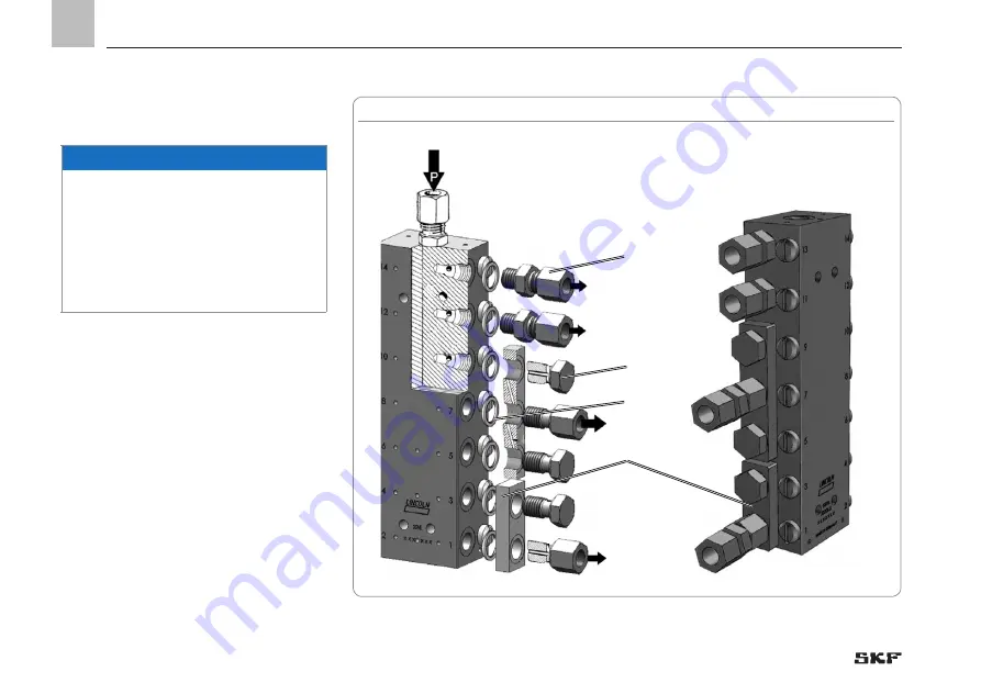
The external combination is realized via con-
necting bars (4). Connecting bars are avail-
able for the 2, 3, 4 and 5 times the output
per outlet.
For external combination of the output, pro-
ceed as follows:
• If necessary, screw closure screws (3)
or outlet fittings (5) out of the metering
device.
• Select the required connecting bars
and install them together with the USIT
gaskets (2), closure screws (3) and check
valves.
Fig. 22 SSVL metering devices with double and triple output
4
3
5
2
Summary of Contents for SSV 10
Page 77: ...Notes...


