


Introduction
P41
-51-
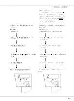
1.The illustration of the sockets positions on
the electric control box is as below(Fig.46/47)
1.
電 控 箱 插 座 位 置 說 明 , 如 下 圖 示(圖
46/47
)
電 控 系統(多 功能標 準型)
ELECTRIC CONTROL SYSTEM
(MULTIFUNCTION STANDARD
TYPE)
圖
46/Fig. 46
圖
47/Fig. 47
電 控 箱 下 方 插 座 位 置 說 明
Sockets positions beneath the electric
control box.
Electromagnet
sensor
Socket
Summary of Contents for 700QD
Page 1: ...700QD 988QD INSTRUCTION BOOK 700Qe 988Qe...
Page 2: ......
Page 3: ......
Page 4: ......
Page 8: ...2 P2...
Page 10: ...P4...
Page 11: ...Introduction 5 P5...
Page 12: ...6 P6...
Page 13: ...Introduction 7 ground P7...
Page 88: ...P82...
Page 89: ...Introduction P83...
Page 90: ...P84...
Page 91: ...Introduction P85...
Page 92: ...P86 74 All machine components must be...
Page 93: ......


