background image

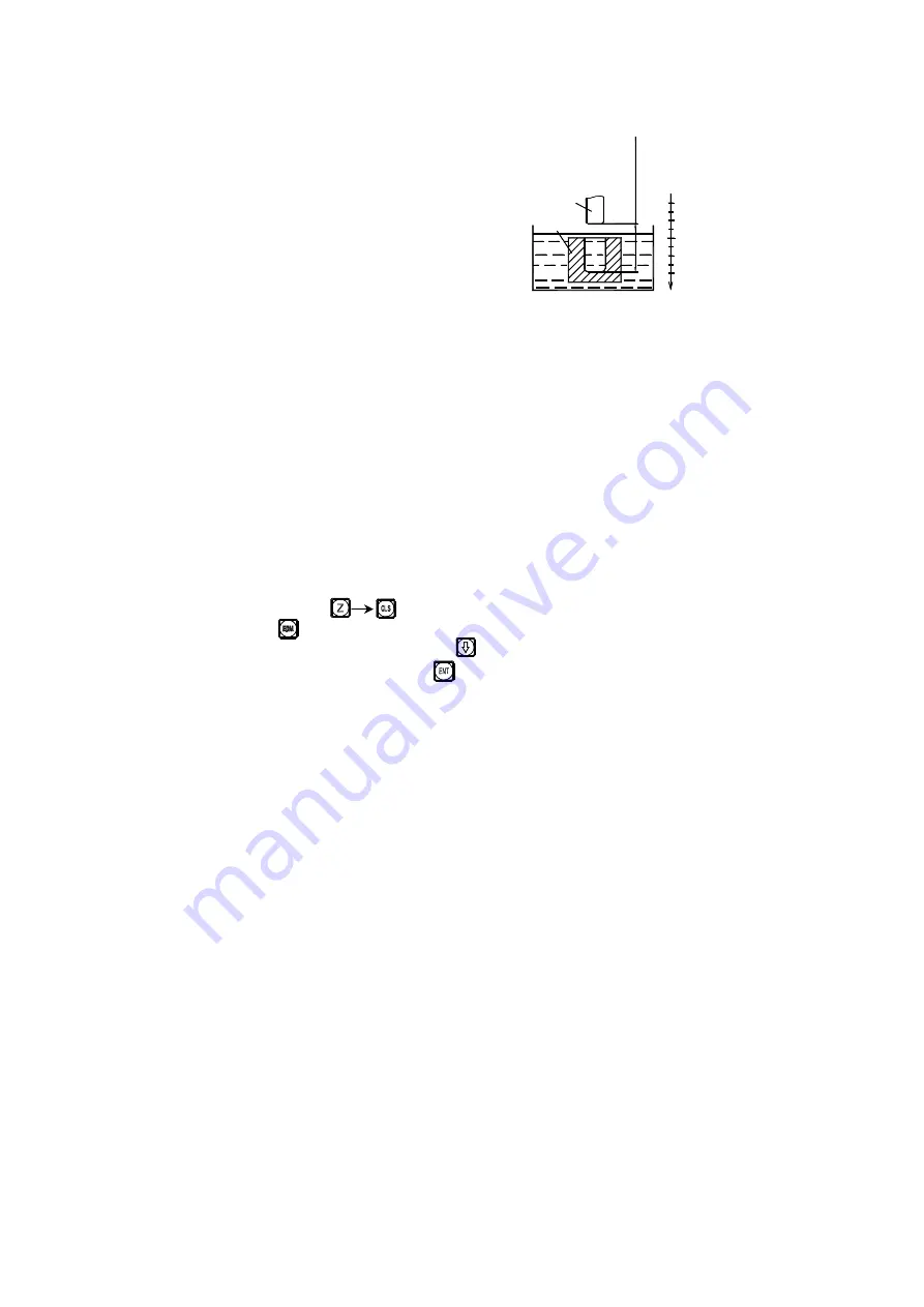
Model SDS2E digital display case also possesses the “negative anti fire 

height” function that other cases of similar kinds cannot offer. This function 
is  delivered  by  a  kind  of  intellectual  location  tracing,  testing  and  protecting 
device. In the positive processing, the electrode surface will be covered by a 
kind of intellectual location tracing, testing and 
protecting device. In the positive processing,   
the electrode surface will be covered by 
accumulative carbon; in case of long time 
processing and overtime processing not under 
control by anybody, such accumulated carbon 
is not cleaned by anyone; then the electrode 
will increase along the negative direction; and once the electrode exceeds the 
liquid surface, it may cause a fire accident and incur losses. This function is 
designed  to  exactly  resolve  this  problem  in  setup.  Once  you  set  “negative 
anti  fire  height”,  when  the  increased  height  of  electrode  exceeds  its  height 
above the depth of processed surface ( i. e. the negative anti fire height), the 
digital  display  case  will  flash  alarm  signal;  meanwhile,  its  exported  signal 
will  automatically  shut  down  the  discharging  processing  machine  to  avoid 
any possibility of fire accident (as shown in Fig. 2).   
 

2. Concrete operating methods: 

See the concrete processing examples 1, 2 and 3 in page 107~109. 

1) Before processing, first set the parameters “negative anti-fir height”,   

“exit mode”, and “processing direction”. 

2) First, move the main axis electrode on Z axis to make it touch work piece 

datum. Reset                  or enter a figure. 

3) Press        button, enter your desired depth value( to be displayed on X axis 

to).  Such  as  10.  Then  press      button  to  confirm  the  input  value. 
Afterwards,  press  the  button        to  exit  from  “Depth”  status.  At  the  same 
time, enter the “EDM” status to conduct processing. 

4) X-axis will display “target value of personal location” 

Y-axis will display “value of depth reached”. Note: Values on Y-axis means 
the depths reached on the work piece by processing. 
Z-axis will display “real time value of personal location”. Note: Values on 
Z-axis mean the values of locations of main axis electrode on Z-axis. 

5) Start processing. The displayed value on Z-axis gradually gets close to the 

)

*

+

,

- .

/

0

1

0

0

2

0

1

3

,

+

4

0

5

6

ne

ga

ti

ve

 a

nt

i-

fi

re

 h

ei

gh

t

Fig. 2 

Summary of Contents for SDS2-2G

Page 1: ...axis milling machine Digital display meter for universal 2 axis grinding machine Digital display meter for universal 3 axis grinding machine Digital display meter for universal 3 axis milling machine...

Page 2: ...ich the user should pay special attention Do not repair or refit the digital display by yourself otherwise a fault or damage might be caused In the case of abnormality please contact your dealer Once...

Page 3: ...ssing Axis displayed Message windows Keys for Axis Selection Key for Cleaning the Displayed Value to Zero Entry Keys for Digits Indicate light of axis selection Function Key for absolute zero position...

Page 4: ...data setting Keys for Axis Selection Message windows Axis displayed Key for taper measure function Key for calling 200tool storeroom Key for input 200 tool storeroom Key for radius diameter switch 0...

Page 5: ...a setting Message windows R Augular Arc Function Key ARC Function Key Indicate light of axis selection SEL SEL Function Key for Mathing Output EDM SEL AB C DE F G H I J K L M Entry Keys for Digits Key...

Page 6: ...d value to zero Function key for getting one half Key for the conversion the meter System British system display Function key for absolute zero position data setting Function key for 200 zero position...

Page 7: ...tion function key Key for Inverting Trigonometric Functions in Calculation function key Square root calculating key in Calculation function key Entry keys for decimal point Entry key plus or minus sym...

Page 8: ...equally dividing PRC Function key Function key for drilling holes along an oblique line Angular surface processing function key Progressive inner chamber processing function key Tool compensation func...

Page 9: ...ed value to zero Function key for getting one half Key for the conversion the meter System British system display Function key for absolute zero position data setting Function key for 200 zero positio...

Page 10: ...ng data Key for cleaning the displayed value to zero Function key for getting one half Key for the conversion the meter System British system display Function key for absolute zero position data setti...

Page 11: ...layed value to zero Key for the conversion the meter System British system display Function key for absolute zero position data setting Function key for 200 zero position Key for taper measure functio...

Page 12: ...splayed value to zero Function key for getting one half Key for the conversion the meter System British system display Function key for absolute zero position data setting Function key for 200 zero po...

Page 13: ...2 2 2MS 2MS 2MS 2MS E1 The Function For 200 Point Subsidiary Zero Position 40 Be the same with Be the same with Be the same with Be the same with 2 2 2 2 2M 2M 2M 2M 2 2 2 2 2MS 2MS 2MS 2MS 2 2 2 2 3M...

Page 14: ...ction Calculator Function 88 Be the same with Be the same with Be the same with Be the same with 2 2 2 2 2MS 2MS 2MS 2MS K Tool Diameter Compensation 91 Be the same with Be the same with Be the same w...

Page 15: ...A1 Basic Functions Be the same with 2 2M 2 2MS 2 2G 2 3M 2 3E...

Page 16: ...check finished enter working mode Note Two axial readout only has X axis and Y axis three axialreadout has X axis Y axis and Z axis The lathe machine readout display LATHE the grinding machine readout...

Page 17: ...direction count Key next step 5 Setting counts direction of axis Y linear encoder Setting method alike axis X Key next step 6 Setting count direction of axis Z linear encoder Setting method alike axis...

Page 18: ...red value is wrong key and enter the correct one again 5 Key If any mistake is found now repeat steps 3 5 6 Move the machine table to the position of 13 and the processing at Point B can start 5 Absol...

Page 19: ...absolute and the relative display mode must be done separately In absolute display mode ALE is displayed on Message Screen It is in absolute display mode when INC is display Message Screen Keying can...

Page 20: ...rmine the center position 2 Key axis key 3 Key 4 Move the machine tool to bring the axis displayed value into zero and the center position is reached 7 M I The mm System inch System Conversion Display...

Page 21: ...s the actual length is larger and symbol means the actual length is smaller Compensation range 1 500 mm m g 1 500 mm m Example The Actual metered length of the machine tool machine table is 1000 mm an...

Page 22: ...mory but the machine tool may have been moved after the event In such a case when the machine is turned on again the working state just before the interruption event will be displayed again but this i...

Page 23: ...A2 Basic Functions Be the sam Be the sam Be the sam Be the same with 2 e with 2 e with 2 e with 2 2L 2L 2L 2L...

Page 24: ...t resolution according to keying different numbers Number key 9 1 2 5 0 Resolution um 0 5 1 2 5 10 Key next step 2 Setting axis Y resolution Setting method alike axis X Key next step 3 Setting counts...

Page 25: ...ay 2 Key 4 Presetting data 1 As figure a shown processing it to the dimension as figure b shown 2 Move the cutting tool onto plane 3 Select the axle key press the button 4 Key enter a value If you ent...

Page 26: ...plane under ALE state Z Z0 axis display 0 1 Cutting tool on D plane 2 Move the cutting tool onto C plane 3 Move the cutting tool onto B plane 4 Key 5 Move the cutting tool onto A plane 6 Move the cutt...

Page 27: ...creen Keying can also realize the conversion between the two display mode and it is also possible to enter the display mode of 200 sets of user coordinates as shown in the following circulating schema...

Page 28: ...measurement systems 1 To repair a spare part with British measurement system the original metric display has to be changed to British system display 2 Key 3 Move drag and start the cutting tool until...

Page 29: ...nsation can be carried in both absolute display mode the message screen displays ALE and relative display mode the message screen displays INC 9 Power Interruption Memory During the processing of a wo...

Page 30: ...y time he she is occupied by other thing the sleep switch can be used to avoid the above mentioned situation In not ALE working state if there a need of Sleep Switch Off key the digital display box wi...

Page 31: ...B Smooth R Be the same with 2 Be the same with 2 Be the same with 2 Be the same with 2 2M 2M 2M 2M 2 2 2 2 2MS 2MS 2MS 2MS 2 2 2 2 3M 3M 3M 3M...

Page 32: ...ng machine This arc Calculation function makes it possible to freely control the smoothness of the circular arc The distance between two adjoining working points is uniform the smoothness of the circu...

Page 33: ...rdinate of Point C 20 20 The coordinate of Point D 30 10 The coordinate of Point E 30 10 The coordinate of Point F 20 20 The coordinate of Point G 30 10 The coordinate of Point H 20 20 In Plane XY XZ...

Page 34: ...ct to the position of the tool just after tool setting and reset In the processing the arc in XZ or YZ plane As shown in Fig b when a flat end milling tool is used the circle center position is the po...

Page 35: ...ition of the last cut feed in the processing of circular arc As shown in Fig b the end angle is 90 if the arc is to be processed from Point E to Point F but 0 when from F to E 9 Determine inner outer...

Page 36: ...If finish the tool setting as shown in Fig a Key Key If finish the tool setting as shown in Fig b Key Key 6 Enter the radius of the circle Key Key 7 Enter the diameter of the tool Key Key 8 Enter the...

Page 37: ...a Tool setting as Fig b 13 Move the machine tool to bring the display value on X and Y axes into zero reach the start point of R 14 Key or and the position of any processing point may come to be disp...

Page 38: ...ARC function 2 Select smooth function Key 3 Select processing plane Key or 4 Select Plane XZ Key 5 Enter the position of the circle center If you use a circular arc milling tool finish tool setting a...

Page 39: ...ool setting as shown in Fig b Key Key 6 Enter the radius of the circle Key Key 7 Enter the diameter of the tool Use a circular arc milling tool Key Use a flat end milling tool Key Key 8 Enter the maxi...

Page 40: ...tool setting as Fig b Use a flat end milling tool setting as Fig a Use a flat end milling tool setting as Fig b 13 Move the machine tool to bring the display value on X and Y axes into zero reach the...

Page 41: ...ed on the message window and the feeding value of every step will be displayed on the unused X Y axis The operator can take the displayed value as reference and what should do is only turning the Z ax...

Page 42: ...n of the circle center Key Key 6 Enter the radius of the circle Key Key Now a circular arc mill is used finish the tool setting as shown in Fig b Plane XZ is selected as the processing plane the spare...

Page 43: ...hine tool to bring the display value on X and Y axes into zero reach the start point of R Key or and the position of last next will be displayed move the machine tool to bring the display values on X...

Page 44: ...C Simple R Be the same with 2 Be the same with 2 Be the same with 2 Be the same with 2 2M 2M 2M 2M 2 2 2 2 2MS 2MS 2MS 2MS...

Page 45: ...oothness is average the simple arc R function may be a good choice In general the processing of a circular arc will be realized in one of the eight ways shown below using end mill or circular arc mill...

Page 46: ...unction 6 Enter the maximal cut MAX CUT When processing an arc in Planes XZ and YZ MAX CUT in the simple R function is defined as the depth of cut in each cut feed in Z axis direction see Fig a the ma...

Page 47: ...d point is B key L R L R the radius of the tool L R the radius of the tool L R L R the radius of the tool L R the radius of the tool L R L1 R L1 R L2 the radius of the tool L2 the radius of the tool L...

Page 48: ...Key Key 7 Enter the maximal cut Key Key 8 Start processing Key Point A as the start point 0 0 Key Point B as the start point 0 0 Key 9 Refer to the display move the machine tool to bring the displayed...

Page 49: ...just the start point Point A or Point B key to enter ARC function Select the simple function key 2 Select the way of the R processing Point A is the start point key Point A is the start point key 3 S...

Page 50: ...direction will alternately displayed on the message window Changing the maximal cut When processing an arc in Plane XZ and YZ MAX CUT is the depth of cut in Z axis If the depth of cut in Z axis is un...

Page 51: ...nging the maximal cut the operator may follow the following operations 1 Change the maximal cut under processing mode Key 2 Enter the changed value of the maximal cut for example 0 5 Key 3 Return to p...

Page 52: ...D Hole Drilling Along An Oblique Line Be the same with 2 Be the same with 2 Be the same with 2 Be the same with 2 2MS 2MS 2MS 2MS...

Page 53: ...e center of the end hole enter this data when MODE L length mode is selected The step length STEP This is the distance between two neighboring the holes This data shall be entered when MODE S step len...

Page 54: ...the function at will just key For the working piece in a it is more convenient to select MODE L In the following we take working piece in b as anther example to shown how to operate when MODE S is sel...

Page 55: ...cessing state 7 Key to display the position of next processing point and then move the machine tool to bring the displayed value on both X and Y axes into zero You can quit the function at will just k...

Page 56: ...he Function For 200 Point Subsidiary Zero Positions Be the same with Be the same with Be the same with Be the same with 2 2 2 2 2M 2M 2M 2M 2 2 2 2 2MS 2MS 2MS 2MS 2 2 2 2 3M 3M 3M 3M 2 2 2 2 3E 3E 3E...

Page 57: ...res with dimensions referred to these point position In these cases if there is only one reference point the working efficiency will be rather low as you have to find out the correct position point by...

Page 58: ...1 2 and 3 in Fig 1 It is possible to enter the display mode of every UCS taking a subsidiary zero position as its original points to perform the processing when need 2 In the display mode of every UCS...

Page 59: ...in memory operation in order that once a power interruption happen in the course the zero position may be tracked back 2 Enter the UCS display mode Two Method Method 1 Key Key Method 2 Key Key 3 Enter...

Page 60: ...he UCS under the relative display mode In Fig 1 we can see that Point O is at the position 80 30 with respect to Point 1 70 40 with respect to Point 2 and 60 40 with respect to Point 3 If the operator...

Page 61: ...absolute state display mode Key 6 Move the machine table of the machine tool to Point 2 X axis display 70 Y axis display 40 7 Enter the display mode of the second UCS Key 8 Clear set the second subsi...

Page 62: ...display mode of the UCS the corresponding subsidiary zero positions may be used to help in the processing It is possible to enter a UCS display mode using key J or When using keys and you may key or c...

Page 63: ...ove the working of the machine tool to Point B X axis display 15 Y axis display 0 7 Process Hole B 8 Move the machine tool to Point C X axis display 0 Y axis display 20 9 Process Hole C 10 Enter the d...

Page 64: ...lute state 2 Reset during a subsidiary zero position is being used A subsidiary zero position is being used of course under the display mode of the corresponding UCS resetting in this state is actuall...

Page 65: ...subsidiary zero position is center between the original subsidiary zero position and the point at which the operation act E2 The Function For 200 Point Subsidiary Zero Positions Be the same with 2 2G...

Page 66: ...e point position In these cases if there is only one reference point the working efficiency will be rather low as you have to find out the correct position point by point more over it may be very diff...

Page 67: ...possible to enter the display mode of every UCS taking a subsidiary zero position as its original points to perform the processing when need 2 In the display mode of every UCS processing with various...

Page 68: ...ion in order that once a power interruption happen in the course the zero position may be tracked back 2 Enter the UCS display mode Two Method Method 1 Key Key Method 2 Key Key 3 Enter the position of...

Page 69: ...osition of Point 2 10 75 and that of to Point 3 10 100 If the operator enters the coordinate of auxiliary zero point at any other point than the zero point under absolute state the display result will...

Page 70: ...inding until the displays on both X axis and Y turn out 0 4 Enter the second user coordinate system Key 5 Process the plane B C Start grinding until the displays on both X axis and Y turn out 0 6 Ente...

Page 71: ...new subsidiary zero position The point at which the resetting operation act become the new subsidiary zero position and the new subsidiary zero position replacing the original subsidiary zero position...

Page 72: ...E3 The Function For 200 Point Subsidiary Zero Positions Be the same with 2 2L...

Page 73: ...ns it is also necessary to have a lot of fixed point positions in order to perform the processing of a series of structures with dimensions referred to these point position In these cases if there is...

Page 74: ...oint O in Fig 1 in next page Set subsidiary zero positions at subsidiary reference points of the working piece for example Points 1O2 and 3 in Fig 1 It is possible to enter the display mode of every U...

Page 75: ...keeping in memory operation in order that once a power interruption happen in the course the zero position may be tracked back 2 Enter the UCS display mode Two Method Method 1 Key Key Method 2 Key Ke...

Page 76: ...from Fig 1 Point O is exactly located at the position of Point 1 20 70 the position of Point 2 30 120 and that of to Point 3 20 130 If the operator enters the coordinate of auxiliary zero point at an...

Page 77: ...been roughly turned and has to be semi subtly turned The unilateral allowance through rough turning is 0 05 the subtle turning will the surface of the work piece to meet the roughness requirements Fir...

Page 78: ...turning of such other end encircle r40 s s s s The Clearing of Subsidiary Zero Positions and Other Related Problems 1 The Clearing of Subsidiary zero positions In absolute state ALE state key 10 times...

Page 79: ...under UCS display mode Turning to one half under the UCS display mode using a subsidiary zero position is actually also resetting a new subsidiary zero position After the operation of turning to one...

Page 80: ...The position of the circle center CT POS means the position of the circle center with respect to the center of the tool just after tool setting and clearing such as the position of Point O with respe...

Page 81: ...or the definition of the start angle ST ANG and end angle ED ANG refer to the section To recognize the start and end angle of a circular arc page 19 Tale the processing of the circular working piece i...

Page 82: ...the arc from 0 to 300 into 5 equal section Key Key next step It is also possible to consider as 7 points in points in used to divide the whole circle into 6 equal sections Key Key next step 6 Enter th...

Page 83: ...The display result for dividing the arc into 6 equal sections 9 Key and the position of next processing point will be displayed just move the machine tool to bring the displayed values on both axes in...

Page 84: ...G Angular Surface Processing Be the same with 2 2MS...

Page 85: ...cessing function plays its role in aligning the reference plane for the bank angle The procedure of aligning for the bank angle At first set the working piece on the machine table with an oblique angl...

Page 86: ...Enter the angle of the angle surface Key Key 4 Move the machine table along X axis Let the metering tool come just in contact with the working piece and adjust the scale reading into zero then move th...

Page 87: ...on When the processing plane is Plane XZ or YZ At first align the spindle of the machine tool for the bank angle finish tool setting and key to enter the angular processing function 1 Select Plane XZ...

Page 88: ...ate Move the machine tool to bring the displayed on X axis into zero refer to the displayed value on Z axis and let the machine table rise or drop by the same value Key or and respectively the positio...

Page 89: ...H The Progressive Progressing of rectangular Inner chamber Be the same with 2 2MS...

Page 90: ...mber and goes on along the arrow direction Operation procedure 1 Key to enter the progressive inner chamber processing function 2 Enter the diameter of the tool DIA 3 Enter the position of the inner c...

Page 91: ...chine table to bring the displayed values on both X and Y axes into zero 7 Key to display the processing position of next step refer to the prompts and move the machine to bring the displayed values o...

Page 92: ...I1 Zero Position Automatic Tracking Be the same with 2 2M 2 2MS 2 3M 2 3E...

Page 93: ...king piece in memory Let s refer to the operations in an example Note The reference point of the grating ruler can be kept it memory and tracked out only when the display box is in the absolute mode A...

Page 94: ...ng the star wheel of the machine tool to move the machine table search the reference point of the grating ruler in X axis direction 5 The reference point of grating ruler is found When FIND X is displ...

Page 95: ...on 6 The X axis reference point of the grating ruler is found as point C in Fig d the position of is displayed as 102 000 7 Move the machine table to bring the displayed value on X axis into zero Poin...

Page 96: ...I2 Zero Position Automatic Tracking Be the same with 2 2G d...

Page 97: ...n of the datum zero mark of the working piece in memory Let s refer to the operations in an example Note The reference point of the grating ruler can be kept it memory and tracked out only when the di...

Page 98: ...ching Y axis the reference point of the grating ruler Key 4 Turning the star wheel of the machine tool to move the machine table search the reference point of the grating ruler in Y axis direction 5 T...

Page 99: ...y to enter the searching state 2 Key 3 Key 4 Searching Y axis the reference point of grating ruler Key 5 Move the machine table along Y axis direction 6 The Y axis reference point of the grating ruler...

Page 100: ...nue to find Y axis absolute coordinate zero point 9 When the display values on both X and Y axis are all zero the point reached is the absolute coordinate zero position O I3 Zero Position Automatic Tr...

Page 101: ...ed the problem will have an easy resolution SDS2 Series digital display box may keep the position of the datum zero mark of the working piece in memory Let s refer to the operations in an example Note...

Page 102: ...the datum zero mark tracking function As shown in Fig a the datum zero mark of the working piece is Point O which is the absolute zero position 1 At fist enter the absolute display mode and reset Key...

Page 103: ...int of grating ruler is assumed as 20 000 Key to quit Searching the datum zero mark of the working point when turn on again power interruption or switching 1 At first to enter the absolute mode then k...

Page 104: ...an continue to find Y axis absolute coordinate zero point 9 When the display values on both X and Y axis are all zero the point reached is the absolute coordinate zero position O J The Function Calcul...

Page 105: ...n X axis Is the Calculation function key key it to enter the Calculation function during using the Calculation function you may quit the function at will just key the same key the key for Calculating...

Page 106: ...ter calculation function Perform the following calculation 10 10 2 5 35 35 Calculate sin 45 0 707 0 707 Calculate arc sin 0 707 44 999 44 999 Make the following calculation The distance AB in the figu...

Page 107: ...Hole B may start Quit the resulted value axis transferring function enter the calculation function again Key Key to quit the calculation function Note When the input value or the resulted value 9999 9...

Page 108: ...ete the processing of the whole length if the tool diameter compensation function is not used The tool diameter compensation function provided in the digital display box can make the related compensat...

Page 109: ...own in Fig 1 1 Key to enter the tool compensation function 2 Select a processing mode preset Start the processing at the position shown in Fig 2 Key Start the processing at the position shown in Fig 3...

Page 110: ...l sides finishes Start the processing at the position shown in Fig 3 Move the machine tool to bring the X axis displayed value into 150 000 and then move to bring the Y axis displayed value into 100 0...

Page 111: ...it will made operator indisposed SDS2 2G special readout for grinding machine has the digital filter function it delays the readout display value when the grinding machine is vibrating The operator ca...

Page 112: ...Note The digital filter function can only be used in INC or ALE mode M 200 Tool Storeroom Be the same with 2 2L...

Page 113: ...sed but the lathe has the frame of adjusting tool Please don t use this function if you haven t the frame of adjusting tool 1 Set a base tool In the state of ALE to clear the display value of the X ax...

Page 114: ...ion of 200 tools storeroom is opened you can lock this function after you continue to touch the key 10 times If the function of 200 tools is locked you can unlock this function after you continue touc...

Page 115: ...ter the using state Key 2 Ensure the base tool Key Default the first tool as the base tool you can also set the other tool as the base tool key number is OK Key can call other tools 3 Call the second...

Page 116: ...u can clear the display value to zero in ALE coordinate system only when using the base tool you can clear the display value to zero in INC coordinate system when using other tools N The Function Of M...

Page 117: ...ce surface Pressing it to make the lever meter point to zero 1 Then entering the function of measure for taper Key 2 Move the lever meter to position B of work piece surface press it to make the lever...

Page 118: ...The display value of Z Z0 axis is angle 4 Quit Key O EDM Matching Output Function Be the same with 2 2E SEL SEL Z Z0...

Page 119: ...igger the coordinate value displayed on Z axis The depth goes further ever since the processing is stared and the displayed value on Z axis increases gradually According the set direction on Z axis th...

Page 120: ...igital display case will flash alarm signal meanwhile its exported signal will automatically shut down the discharging processing machine to avoid any possibility of fire accident as shown in Fig 2 2...

Page 121: ...he setup of operators there are 2 kinds of exit modes 7automatic mode means automatically exit from the processing status of spark machine and return to the display status before such processing 8paus...

Page 122: ...t is necessary to change the originally set DEPTH ERRHIGH or EXIT MODE and PROCESSING DIRECTION the operator can press button to enter the setup mode When the message screen displays DEPTH you can re...

Page 123: ...rocessing Example 2 Work piece shown in the processing drawing c Please make sure the processing direction is positive 1 First move the main axis electrode to make it touch the work piece datum as sho...

Page 124: ...ey 3 Enter the depth value Key Key 4 Start processing 5 Reach the target value EDM E display lasts for 3 seconds and then exits automatically 5 Example of Negative Processing Example 3 Work piece as s...

Page 125: ...for 3 seconds and then exits automatically 6 A Combined Use of PCD function and EDM function PCD and EDM functions can be used in a combination The operator can first use the PCD function under the w...

Page 126: ...erly 3 Power voltage selection AC 85V 220V 15 50 Hz 60 Hz 4 Power consumption 25VA 5 Working temperature 0 45 6 Storage temperature 30 70 7 Relative humidity 90 20 5 8 Weight 3 2 kg 9 There must not o...

Page 127: ...ruler 1 Check power wire then switch on power supply 2 Close the power switch 3 Mains voltage should be within 60 260V 4 Disconnect plug of grating ruler Enclosure of digital display meter is charged...

Page 128: ...Repair the grating ruler 3 Too much gap between reading head of grating ruler and ruler body 3 Repair the grating ruler 4 Metal hose parts of grating ruler plugs hoses connectors burnt squeezed broke...

Page 129: ...t elasticity of carriage steel wire inside reading head of grating ruler 4 Repair the grating ruler Structural principle Our linear encoder and digital readout are high technologic production that is...

Page 130: ...Production package bill 1 A piece of SDS series digital readout 2 A piece of power wire 3 A copy of operating instruction 4 A copy of verified certificate 5 A piece of dustproof cover...

Reviews: