

2GIG
®
GC3 Security & Automation System
2GIG-SP2-GC3 | Wireless Touch Screen
10014895 B | Proprietary & Confi dential
Nortek Security & Control | 1950 Camino Vida Roble, Suite 150 | Carlsbad, CA 92008-6517 | USA | 800-421-1587 | www.nortekcontrol.com
Copyright © 2017 Nortek Security & Control LLC
PRINTER’S INSTRUCTIONS:
INSTALL INSTRUCTIONS, 2GIG SP2 GC3 (ENGLISH) - P/N: 10014895 B - INK: BLACK - MATERIAL: 20 LB MEAD BOND - SIZE: 8.500” X 11.000” - TOLERANCE: ± .125” - SCALE: 1-1 - SIDE 1 OF 2
The Wireless Touch Screen (2GIG-SP2-GC3) is a wall-mounted, full-color, touch
screen interface that provides many of the same easy-to-use keypad functions
available on the Control Panel. It is designed for indoor use only and gives users
the ability to arm and disarm the system and see the status of sensor zones.
IMPORTANT:
This keypad does not support UL 985 installations
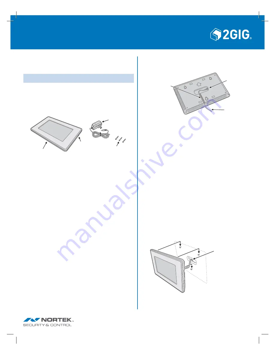
Box Contents
Verify that the package includes the following:
»
1— SP2 Wireless Touch Screen
»
1—AC
Adapter
»
3—Anchorless
Screws
Minimum Requirements
For successful communications, the system must meet these minimum
requirements:
»
The GC3 Control Panel must be running Version 3.0.2 or higher.
Recommended Tools
»
Drywall Saw (or equivalent)
»
Pencil
»
Screwdriver
»
Drill with 3/16” masonry bit (if mounting on masonry)
Mounting the SP2 Touch Screen to the Wall
Note:
As an alternative to wall mounting, the SP2 Touch Screen can also
be set on a desktop using the 2GIG-CP-DESK Desktop Kit.
To mount the SP2 Touch Screen to the wall:
1.
Use the template included to mark the three locations for the mounting
screws on the wall.
2.
If the power cable is going to be recessed in the wall, mark the location of
the wire access slot and use a drywall saw to cut out the oval hole.
3.
The anchorless screws do not require pre-drilling when used in wallboard.
If mounting on concrete, grout-fi lled or hollow block, brick, or plaster, pre-
drill with a 3/16” masonry bit.
4.
Drive the three mounting screws into the wall, leaving the heads about 1/4”
out.
SP2 Touch Screen Power Connection
There is a power input jack on the rear of the SP2 Touch Screen. The barrel
connector on the end of the power supply cable plugs into the power input jack.
POWER
SUPPLY
CABLE
POWER
INPUT
JACK
FOR SURFACE
WIRING, ROUTE
POWER SUPPLY
CABLE HERE
Connecting the SP2 Touch Screen Power
In wall-mount installations, the power cable from the power supply can be surface
run to the SP2 Touch Screen, or recessed in the wall entering through the wire
access slot on the back of the SP2 Touch Screen.
Surface Power Wiring
Follow these steps for surface wiring:
1.
Plug the power supply cable barrel connector into the power input jack on
the rear of the SP2 Touch Screen.
2.
Route the power supply cable into the wire retaining trough on the rear of
the SP2 Touch Screen.
3.
Plug the power supply into an un-switched AC outlet.
4.
Attach the SP2 Touch Screen to the wall by hanging it on the three screws.
Recessed Power Wiring
Follow these steps for recessed wiring:
1.
Route the power supply cable into the wall from the power supply’s
location.
2.
Pull the power supply cable out through the wire access slot cut in the
wall.
3.
Plug the power supply cable barrel connector into the power input jack
on the rear of the SP2 Touch Screen.
4.
Plug the power supply into an un-switched AC outlet.
5.
Attach the SP2 Touch Screen to the wall by hanging it on the three
screws.
ROUTE POWER
CABLE THROUGH
CUTOUT IN WALL
HANG TOUCH SCREEN
ON MOUNTING SCREWS
Figure 3
SP2 Touch Screen Recessed Power Wiring
Figure 2
SP2 Touch Screen Power Input Connector
POWER
BUTTON
MOUNTING
SCREWS (3)
POWER
SUPPLY
WIRELESS
TOUCH
SCREEN
Figure 1
SP2 Wireless Touch Screen & Accessories


