User Manual
EM303A General Purpose Inverter
102
DC brake time
≠
0, then DC brake enabled.
F3-25
Different setting values can define different DC brake torques at stop.
★
When the parameter
≤
30.00, the percentage base is the rated output voltage of
inverter. While, the DC brake controls the DC voltage generated by motor
windings.
★
When the parameter
≥
30.01, the percentage base is the rated output current of
inverter. While, the DC brake controls the DC current generated by motor
windings.
F3-26
when DC brake command given by the terminal is active at stop or the output
frequency reaches the setting value of F3
-
24 in the process of ramp to stop. DC
brake enabled after the time set by F3-26 is up.
F3-27
Set DC brake time at stop. If F3-27=0.00, the DC brake is disabled at stop.
1.
If there is a stop DC brake signal of external terminal, then the stop DC brake
time takes the greater between the active time of the DC brake signal of
external terminal at stop and the setting time in F3-27.
2.
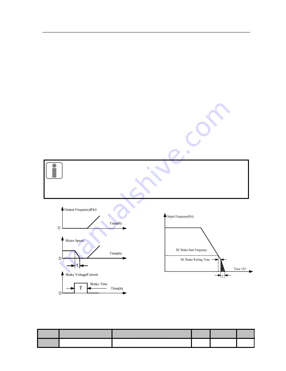
DC brake process at stop is as shown in Figure 7-11.
z
For heavy load, regular deceleration cannot stop motor fully due to inertia,
and motor could stop by prolonging the DC brake time or increasing DC brake
current at stop.
z
For potential energy load, DC brake current control mode cannot be applied due to
the rising time of current.
Figure 7-10 DC Brake Process at Start
Figure 7-11 DC Brake Process at Stop
No.
Function
Range
Unit
Default
Type
F3-28
Lower Limit Frequency
0: Run as per lower limit frequency
0000
〇


