381295/B
23
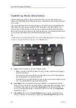
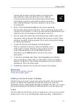
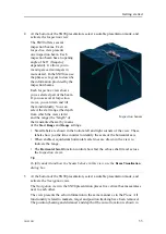
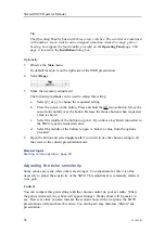
User Setting Buttons
, assign one predefined setting to each button on the Operating
Panel. The
Operating Panel
page is located in the
Installation
dialog box.
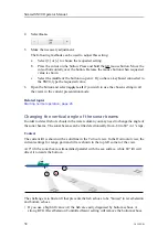
D
F1 F2 F3
: Press one of the
Fx
buttons to apply a predefined function. To choose
which
function to apply open the
Operating Panel
page. Under
Button Options
,
assign one function to each
Fx
button on the Operating Panel.
Screen Capture
: Press this button to make a copy of the current SN90 presentation.
You can choose either a single screen capture or a sequence with multiple screen
captures. Open the
Screen Captures
dialog box to select screen capture mode.
E
Joystick
: Press the joystick forward to increase the tilt angle in the active view. Turn
the button on the top of the joystick to change the bearing in the active view.
F
Mouse buttons
: These buttons correspond to the two most common buttons on a
standard computer mouse. When an instruction tells you to "select" or "left-click",
press the left button. When an instruction tells you to "right-click", press the right
button.
G
A hull unit may be provided as an optional method to lower and hoist the transducer.
Use these buttons to lower and hoist the transducer. While the transducer is moving
the indicator lamp flashes, and an audible signal is sounded. When the requested
position has been reached, the indicator lamp is lit, and the audible signal stops.
•
Up
: Press
Up
to hoist the transducer to its upper position.
•
Middle
: Press
Middle
to place the transducer in a predefined middle position.
•
Down
: Press
Down
to lower the transducer to its bottom position.
H
Rotary switches
: Turn a rotary switch to apply a predefined function. To choose
which
function to apply open the
Operating Panel
page. Under
Rotary Switch
Options
, assign one function to each rotary switch on the Operating Panel.
I
Use these buttons to place markers in the current active view.
•
Marker
: Press
Marker
to place a generic marker in the active view. One or more
markers can be placed in the view to identify specific echoes. Each marker
is shown as a small triangle with or without a short identifying label. It is
positioned based on the two known axes in the view as well as the tilt and
bearing of the current ping.
•
Circle Marker
: Press
Circle Marker
to place a circular marker in the active view.
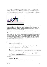
The circle is drawn with the same diameter as your purse. By means of the circle
you can see the size of the school relative to your purse.
•
Gear
: Press
Gear
to place a gear symbol in the active view. The gear symbol is
provided as a tool to help you plan and shoot the purse seine. The symbol is
intended to be used in a structured sequence that starts when you plan to shoot
the purse seine.
J
Press these buttons to start position or target tracking.
•
Position Track
: Use the trackball to control the cursor in the SN90 user
interface.A position track permits the SN90 to automatically control the tilt and
bearing based on the movements of your vessel. It locks on a position defined by
Summary of Contents for SN90
Page 2: ......
Page 186: ... 2020 Kongsberg Maritime ...
Page 187: ......
Page 188: ...Simrad SN90 Purse Seine and Trawling sonar Operator Manual ...

