background image

| 5

Basic Operation | 

IS40 PRO Operator Manual

Turning the IS40 PRO on and off

The IS40 PRO has no 

Power

 key, and it will be running as long as 

the power is connected.

Display Lighting

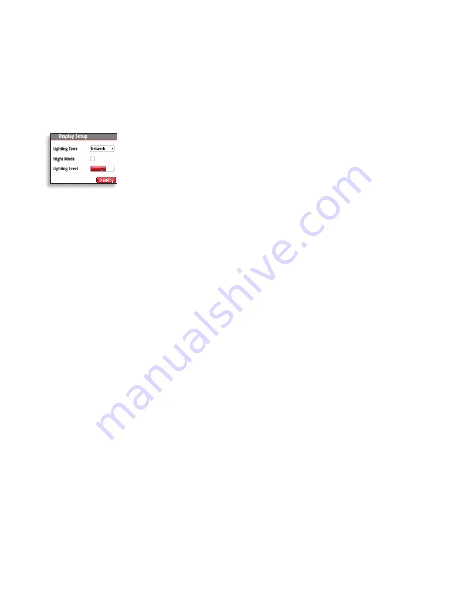
Press and hold the 

Enter

 key for 3 seconds to display the Display 

Setup dialog. 
The Lighting Level option is active by default, and you need to press 
the 

Enter 

key to select the other options in the dialog.

1. 

Use the 

Arrow

 keys to select an option.

2. 

Press the 

Enter

 key to confirm the selection. The frame around the option 

is red by default and will turn green when selected to adjust values.

3. 

Use the 

Arrow

 keys to adjust the value.

4. 

Confirm the selection by pressing the 

Enter

 key.

Lighting zone

Set the lighting zone for the display. All units in the selected 
Lighting Zone will mirror each others light settings. Default setting 
is Network.

Night mode

Change the display to Night Mode color pallet. All displays in the 
selected Lighting Zone will also change to Night Mode.

Lighting level

Adjust the backlight level from 0-10.


¼

Note: 

When set to level 0, the display backlight will be off and keys 

backlight will be at a minimum. 
When the IS40 PRO is powered on, the Lighting level will be as set 
before the unit was powered off. The Night Mode option will be on 
if it was enabled when the unit was powered off.

Standby

Turns off the backlight for keys and display. Press any key to return 
to normal operation.

Summary of Contents for IS40 PRO

Page 1: ...ENGLISH IS40PRO Operator Manual...

Page 2: ......

Page 3: ...VIOLATE THE LAW Governing Language This statement any instruction manuals user guides and other information relating to the product Documentation may be translated to or has been translated from anoth...

Page 4: ...installation or use of the system so it is essential for the person in charge of the installation to be familiar with the relevant requirements as well as with the contents of the manuals which covers...

Page 5: ...tional data pages 12 Customizing a page 14 Setup 14 Sources 15 Device list 16 Remote Displays 16 Calibration 21 Time Date 22 Units 22 Language 22 Display setup 22 Show graphics 23 Damping 23 Decimal p...

Page 6: ...he Rudder Angle page is Wheelmark approved The IS40 PRO Display 1 4 3 2 1 Enter Backlight key Used to enter the main menu select sub menus and confirm selection Hold 3 seconds for illumination setting...

Page 7: ...s to adjust the value 4 Confirm the selection by pressing the Enter key Lighting zone Set the lighting zone for the display All units in the selected Lighting Zone will mirror each others light settin...

Page 8: ...the data is out of scale there will be no data reading on the display RudderAnglepagewith missingdata RudderAnglepagewith dataoutofscale Digitalpagewithmissing data Setting up the Rudder Angle page F...

Page 9: ...s and devices on the network Note Only the Rudder Angle pages are Wheelmark approved Below is an example with six additional pages enabled Each press of the Page key will change the current data page...

Page 10: ...Wheelmark approved Basic Speed Depth Two line data display Boat speed and Depth 1 Refresh indicator 2 Boat speed 3 Depth 1 2 3 Wind 1 Apparent wind speed AWS 2 Refresh indicator 3 True wind speed TWS...

Page 11: ...Off track limit 6 Track 7 Boat position from track 8 Cross track distance graphic 9 Cross track distance XTD 10 Course over ground COG 11 Bearing to waypoint indicator 3 8 4 9 7 6 1 2 5 10 11 Depth Hi...

Page 12: ...me 8 Boat position Lati tude Longitude 9 Coordinate system 3 6 7 1 5 8 4 2 9 Note GPS information relies on a suitable GPS connected to the network and selected on the display as the current Position...

Page 13: ...ted auto scroll automatically scrolls between the enabled pages at a timed interval predetermined by setting the desired scroll time in the auto scroll settings menu Include in auto scroll To include...

Page 14: ...der 45 page can only be replaced by Rudder 70 page Customizing a page The content of the predefined pages can be changed when the page is enabled You can replace the page with another predefined page...

Page 15: ...prefered display page The image below shows how to change a page when using the Two Line template Changing an analog display scale For some full screen analog displays not Rudder Angle pressing the Ar...

Page 16: ...sensor replaced or a network reset Auto select The Auto select option will look for all sources connected to the instrument system If more than one source is available for each item the display will a...

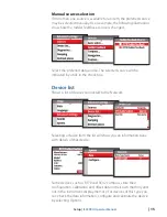
Page 17: ...ted source will be indicated by a tick in the check box Device list Shows a list of devices connected to the Network Selecting a device from the list will show you an information pane with details of...

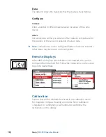
Page 18: ...sor data Note Some devices can be configured further If a device transmits other data it may be shown on this page also Remote Displays When B G HV displays are available on the network they can be co...

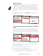
Page 19: ...Page key is used for left right digit selection Auto Boat speed calibration via reference to GPS SOG value This is an AutoCal facility that uses speed over ground SOG from your GPS and compares the av...

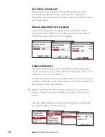
Page 20: ...e value Select OK once complete Distance Reference This option enables the user to calibrate the log accurately and simply Calculations are performed by the display that works out the boat speed over...

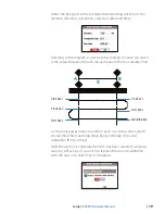
Page 21: ...tance for each run as measured from a suitable chart StartRun1 StopRun1 StopRun2 EndCalibration StartRun2 StartRun3 A B X As the boat passes marks A and B on each run instruct the system to start Star...

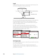
Page 22: ...asier to see the available depth taking into account the draught of the boat The offset value to be entered should represent the distance between the face of the depth transducer and the lowest part o...

Page 23: ...t s heading must be referenced to for example a calibrated bowl compass The offset value will be the difference between the known source and the currently displayed heading Enter this value as the off...

Page 24: ...guages to suit your preference Display setup Set the Lighting Zone enter Night Mode and change the Lighting Level See Display Lighting on page 5 Show graphics It is possible to turn on or off backgrou...

Page 25: ...e displayed with Sounds Turn the keypress sound on or off System From the system menu there are several options to reset the system and get the current software information Network reset Resets the so...

Page 26: ...list shows the network bus status bus load as a percentage as well as quantity and type of data messages Note We recommend that you use this diagnostic tool as a basic overview of the network status F...

Page 27: ...bons such as diesel petrol etc Always put on the weather cover when the unit is not in use Checking the keys Make sure that no keys are stuck in the down position Checking the connectors The connector...

Page 28: ...r Black Display Size 4 1 Diagonal 4 3 Aspect ratio Type Transmissive TFT LCD White LED backlight Resolution 320 x 240 pixels Illumination White day mode Red night mode Environmental Protection IEC 609...

Page 29: ...vel 4 Pages Rudder 45 70 Basic speed depth Wind composite Replace page Select page format Steering Enable page Depth history Include in auto scroll GPS Auto scroll settings Start auto scroll Highway S...

Page 30: ...Time format Local time Units List Language List Advanced settings Sources List Device list Model ID Serial No Diagnostics List Damping List Decimal places Speed Sea temp Use COG as heading Use SOG as...

Page 31: ......

Page 32: ...988 10840 001...

Reviews: