Troubleshooting and Maintenance
974-24007001/5.0
89
(monitor by the TTM) is first detected then intentionally turned off and then detected again
by changing the values being uplinked and re-written back to the DACs. The final values
written to the DACs directly represent what we refer to as the “Cable Gain Numbers” i.e.,
example “6, 23” to compensate for the signal loss through the 3rd wire.
The most important steps regarding the Downlink and Uplink communication between the
host software, the TTM and the sonar head is completed. If any problems were detected
with the TTM/ LF1 telemetry, the LF1 telemetry board in the sonar head, the CPU board,
the transmitter or the receiver boards the cable calibration would have failed.
Motor Calibration
After the downloading of the head parameters is completed the host software via the CPU
board will request a motor calibration. The motor driver board will come online and
calibrate the motor with a series of rotations in order to detect the optocouplers located in
the motor housing and set-up each quadrant. The 4 quadrants and calibration numbers will
be recorded in the host software “info” page.
If the motor calibration fails the problem may be with the motor controller board of the
optocouplers located in the motor housing.
Sensors Info Request
The next step the host must know what is connected to the system in respect to the type of
sensors. A command requesting is downlinked to the head CPU board, the CPU will
request the info from the sensors controller board, e.g., Catch sensors, temp and depth,
Door Spread sensors etc. After the controller board has completed the detection the info is
uplinked back to the host software via the CPU, LF1 telemetry board in the sonar head,
then uplinked to the TTM via the LF1 telemetry board.
After the Host has received the information then the sensors page including the data will be
displayed on the sonar image.
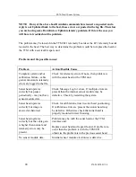
If no sensor information is displayed on the sonar image you may have a problem with the
sensor controller board. If the internal sensors are displayed but no external sensors are
shown then the problem may be with the catch hydrophone receiver or the associated
circuits. If only some of the sensors are displayed you may have a problem with a specific
sensor that was not detected. You will have to troubleshoot the problem.
User Settings
If all OK and no errors are posted into the log files then the host will download the selected
“User Setting” to the head.
Summary of Contents for FS70 -
Page 2: ......
Page 3: ...974 24007001 5 0 I 974 24007001 5 0 FS70 Trawl Sonar System Operator manual...
Page 44: ...FS70 Trawl Sonar System 34 974 24007001 5 0 Click button on the recording tool bar...
Page 56: ...FS70 Trawl Sonar System 46 974 24007001 5 0 3 2 7 7 PI 40 kHz Channel Sensors Setup...
Page 103: ...974 24007001 5 0 93...
Page 104: ...FS70 Trawl Sonar System 94 974 24007001 5 0...
Page 105: ...974 24007001 5 0 95...
Page 106: ...FS70 Trawl Sonar System 96 974 24007001 5 0...
Page 107: ...974 24007001 5 0 97...
Page 108: ...FS70 Trawl Sonar System 98 974 24007001 5 0...
Page 109: ...974 24007001 5 0 99...
Page 110: ...FS70 Trawl Sonar System 100 974 24007001 5 0 This page is left intentionally blank...
Page 112: ...FS70 Trawl Sonar System 102 974 24007001 5 0 This page is left intentionally blank...
Page 113: ...2010 Kongsberg Mesotech...
Page 114: ...SIMRAD...


