Troubleshooting and Maintenance
974-24007001/5.0
83
To test for this the trawl cable should be disconnected from the FS system and a voltage
meter connected to the trawl unit end of the cable. If water is present, then there may be a
reading of 2 - 3 volts.
5.4.6
Telemetry Errors
In the normal operation of the FS Trawl Monitoring system commands are sent from the
processor unit down the trawl cable to the trawl unit electronics and acknowledgments are
then sent back up to the processor unit. Some error checking of these commands is
performed to monitor the performance of the Uplink and Downlink telemetry.
Telemetry errors can result from noise induced on the trawl cable due to interference or
problems with the 3
rd
wire trawl cable or trawl unit electronics.
Though a few telemetry errors are quite common and acceptable, an excessive number of
errors will adversely affect the sonar operation and may indicate a problem that will
eventually cause a system failure.
The most common type of telemetry errors is time-outs. This problem indicates the trawl
unit electronics are not responding to the processor unit or the integrated sensor module is
not responding to the sonar head.
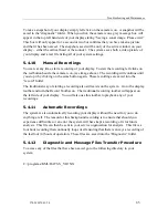
If the processor unit displays changes in the “Baud Rate” (highlighted in red and flashing)
the change indicates that the Uplink signal to the processor may have a problem then refer
to the “Message Log” file and record the “Errors” including the cable gain number values
and make note of any other failure.
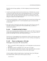
If no errors are recorded in the “Message Log” file, then re-set the baud rate to 115.2 kbps
and implement a system re-calibration. Next record the results obtained. The changes may
have been caused by noise or other interference.
5.4.7
Diagnostic Recordings
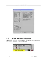
The system will save your screen displays in three different ways. Two of these ways are
manually started by the operator and the third is automatically managed by the system. All
three methods create files on the system which can be sent to your service provider for
analysis.
5.4.8
System Info Page
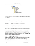
The System Info Page provides all the pertinent information required by the factory in order
to assist you in troubleshooting the FS system on-board the vessel.
Summary of Contents for FS70 -
Page 2: ......
Page 3: ...974 24007001 5 0 I 974 24007001 5 0 FS70 Trawl Sonar System Operator manual...
Page 44: ...FS70 Trawl Sonar System 34 974 24007001 5 0 Click button on the recording tool bar...
Page 56: ...FS70 Trawl Sonar System 46 974 24007001 5 0 3 2 7 7 PI 40 kHz Channel Sensors Setup...
Page 103: ...974 24007001 5 0 93...
Page 104: ...FS70 Trawl Sonar System 94 974 24007001 5 0...
Page 105: ...974 24007001 5 0 95...
Page 106: ...FS70 Trawl Sonar System 96 974 24007001 5 0...
Page 107: ...974 24007001 5 0 97...
Page 108: ...FS70 Trawl Sonar System 98 974 24007001 5 0...
Page 109: ...974 24007001 5 0 99...
Page 110: ...FS70 Trawl Sonar System 100 974 24007001 5 0 This page is left intentionally blank...
Page 112: ...FS70 Trawl Sonar System 102 974 24007001 5 0 This page is left intentionally blank...
Page 113: ...2010 Kongsberg Mesotech...
Page 114: ...SIMRAD...

