FS 70 Installation Instructions
974-24007001/5.0
69
4.3
System Set-up and Testing using the test
cable
Initial power-up, set-up and test of the system should be made with the trawl unit connected
to the PWR/TTM module using the supplied test cable. The 3-pin MS connector of the test
cable is attached to the connector labelled “TEST CABLE” located on the front panel of the
PWR/TTM unit. The other end of the test cable is plugged into the 2-pin connector on the
sonar head of the trawl unit.
4.3.1
FS Processor & TTM Communication Set-Up
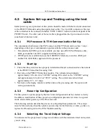
The commnunication between the FS Processor and the TTM unit can be achive 3 ways
depending on the type of communication ports available in the processor unit:
1.
If standard serial COM ports are available you may use a RS232 Null Modem cable,
KML part number 144-0217, supplied with the processor.
2.
If USB ports are available then use the USB/RS232 telemetry converter, KML part
number 901-80010000, supplied with the processor.
4.3.2
Start Up
1.
Check that the system has been properly installed and that all connections have been made
to the PWR/TTM and the Processing Unit.
2.
First turn on the PWR/TTM interface module. The voltmeter should display
approximately 120 volts if on “120VDC” setting, 200 volts if on the “200VDC” setting
and approximately 60 volts if on “TEST” setting. The current meter should read
approximately 0.15 – 0.7 amps.
3.
Next turn on the display monitor, and then turn on the processing unit. The system will
start up automatically.
4.3.3
Power-Up Configuration
For the system to operate properly the trawl unit configuration must be selected correctly.
In addition, modification of these power-up configuration parameters is done in a special
mode selected after power-up of the Processor unit.
The following sections describe the process of configuring these parameters. These steps
must be followed only when the system is powered-up for the first time or when you have to
replace the Processing unit or the TTM Module assembly.
4.3.4
Selecting the Trawl Output Voltage
You must select the proper trawl voltage in accordance with the underwater trawl unit system
you are using,
Summary of Contents for FS70 -
Page 2: ......
Page 3: ...974 24007001 5 0 I 974 24007001 5 0 FS70 Trawl Sonar System Operator manual...
Page 44: ...FS70 Trawl Sonar System 34 974 24007001 5 0 Click button on the recording tool bar...
Page 56: ...FS70 Trawl Sonar System 46 974 24007001 5 0 3 2 7 7 PI 40 kHz Channel Sensors Setup...
Page 103: ...974 24007001 5 0 93...
Page 104: ...FS70 Trawl Sonar System 94 974 24007001 5 0...
Page 105: ...974 24007001 5 0 95...
Page 106: ...FS70 Trawl Sonar System 96 974 24007001 5 0...
Page 107: ...974 24007001 5 0 97...
Page 108: ...FS70 Trawl Sonar System 98 974 24007001 5 0...
Page 109: ...974 24007001 5 0 99...
Page 110: ...FS70 Trawl Sonar System 100 974 24007001 5 0 This page is left intentionally blank...
Page 112: ...FS70 Trawl Sonar System 102 974 24007001 5 0 This page is left intentionally blank...
Page 113: ...2010 Kongsberg Mesotech...
Page 114: ...SIMRAD...

