


–remove the cover (6) of the outer
casing;
– remove the screw that fastens
each burner (7) t o the burner
ramp, sliding it out of the combu-
stion chamber;
–loosen off the screws that fasten
the upper front inner panel (4) and
remove the panel;
–r emove t he cleaning plat e (5),
unscrewing the screws that fasten
to the smoke chamber;
–using a plastic tube-brush, clean all
smoke passages and ducts;
–once the boiler body has been clea-
ned, next clean the burners, blowing
in a jet of air;
–check positioning of electrodes and
their state of wear;
–clean the connection to the chimney
and check efficiency of flue.
–after assembly of all the gas con-
nections, these must be tested for
soundness, using soapy water or
appropriate products. DO NOT USE
NAKED FLAMES.
Preventive
maintenance
and
checking of efficient operation of
equipment and safety devices must
be carried out exclusively by the
authorized engineer.
4.6
FAULT FINDING
Electric power is reaching control
panel, but boiler fails to start.
–Check that gas is reaching boiler.
–Check regulating and safety thermo-
stats are closed.
–No gas is reaching pressure switch.
– Check electronic equipment is opera-
ting properly. If necessary, replace.
Boiler keeps turning on and off, and
red warning lamp on panel keeps
going on and off.
–Check for pressure drops in the gas
suppl y sy s t em when t he boiler
starts up. The value of the dynamic
pressure at the gas valve inlet must
not be less than 9.7 mbar.
–Check the gas-line.
–Check for load losses of any solenoid
valves and safety devices installed
upstream of the gas unit.
–Check setting and operation of the
gas pressure switch; if necessary,
replace.
Discharge spark present on ignition
electrode, but burner fails to light.
– Air is present in the pipe upon first
ignition or after long periods of lay-off.
–Check whether the rectifier card on
the connector that supplies the gas
solenoid valve is working properly. If
necessary, replace.
–Valve coil has a break in the winding;
replace.
No discharge spark noted on ignition
electrode.
–Electric wire is interrupted or not
properly fastened to terminal 10.
–Equipment has transformer burnt
out; replace.
Flame detection failure.
– The positions of live and neutral on
the terminal block are not respected.
–Check whether earth wire has been
connected.
–The electrode wire is interrupted or
is not well fastened to terminal 8.
–The sensing electrode is earthed.
–The electrode is badly worn out or
the ceramic protection is damaged;
replace.
–The equipment is faulty; replace.
–With live/live electric lines, it may
be necessary to install the transfor-
mer code 6239700.
Boiler operates only at nominal pres-
sure and does not reduce pressure.
–Check whether there is voltage at
both ends of coil.
–The coil has a break in the winding;
replace.
–The rectifier card that supplies the
coil is interrupted; replace.
–There is no differential on setting of
the two contacts of the regulating
thermostat; replace.
–Check calibration of reduced pres-
sure adjusting screw (4 fig. 19) of
coil assembly.
Boiler tends to turn off easily and
forms condensate.
–Check that the flame of the main
burner is well regulated and that
gas consumption is proportional to
boiler output.
–Poor ventilation of premises where
boiler is installed.
–Flue with insufficient draught or not
meeting requirements.
–The boiler works at too low tempe-
ratures. Adjust the boiler thermo-
stat to higher temperatures.
Thermostat switches boiler back on
with too high temperature difference.
–Replace r egulating t her mos t at
since it is out of calibration.
59
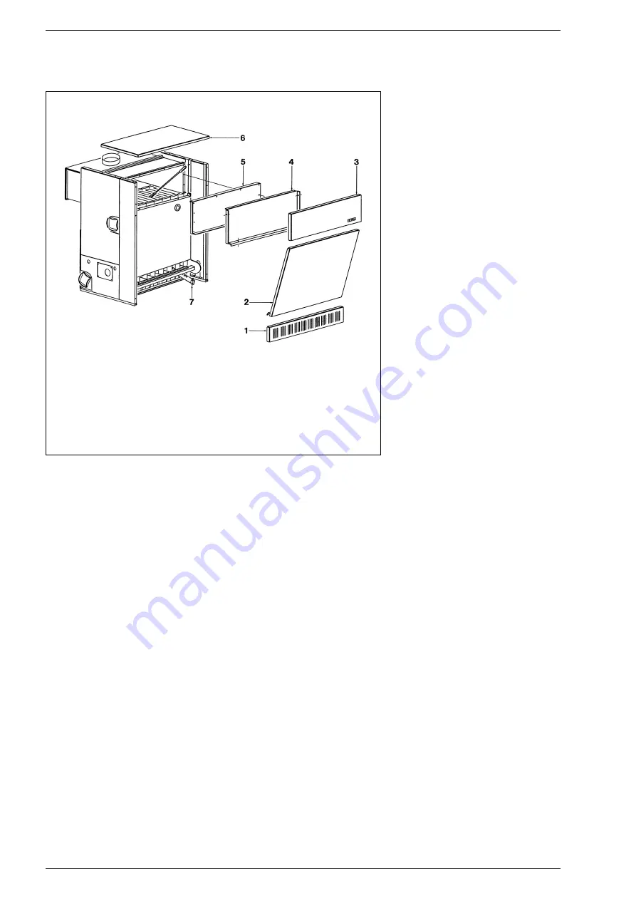
KEY
1 Casing base strip
2 Casing door
3 Upper front panel
4 Upper front wall
5 Smoke chamber
cleaning plate
6 Casing cover
7 Burner
Fig. 21
Summary of Contents for RS 10
Page 1: ...RS IT ES GB PT...


