30
4
COMMISSIONING, USE and MAINTENANCE
INSTALLATION, SERVICING AND REPAI-
RS MUST BE CARRIED OUT BY ONLY AU-
THORISED PERSONS
COMMISSIONING INSTRUCTIONS
A Commissioning checklist is included
in this manual and must be completed
by the engineer at the time of commis-
sioning.
General
Please note: the combustion for this ap-
pliance has been checked, adjusted and
preset at the factory for operation on the
gas type defi ned on the appliance data
plate. However, it is advisable to check
for correct combustion having fi rst che-
cked the following.
• That the boiler has been installed in
accordance with these instructions
• The integrity of the fl ue system and
the fl ue seals
•
The integrity of the boiler combustion
circuit
Proceed to put the boiler into operation
as follows:
Check the operational (working)
1.
gas inlet pressure.
Set up the boiler(s) to operate at
maximum rate as described in
4.5.1(chimney sweep)
With the boiler operating in the ma-
ximum rate condition check that the
operational (working) gas pressure
at the inlet gas pressure test point
(see fi g 16 item 1) complies with the
requirements of table 1.3.
Ensure that this inlet pressure can
be obtained with all other gas ap-
pliances in the property working.
Combustion check
2.
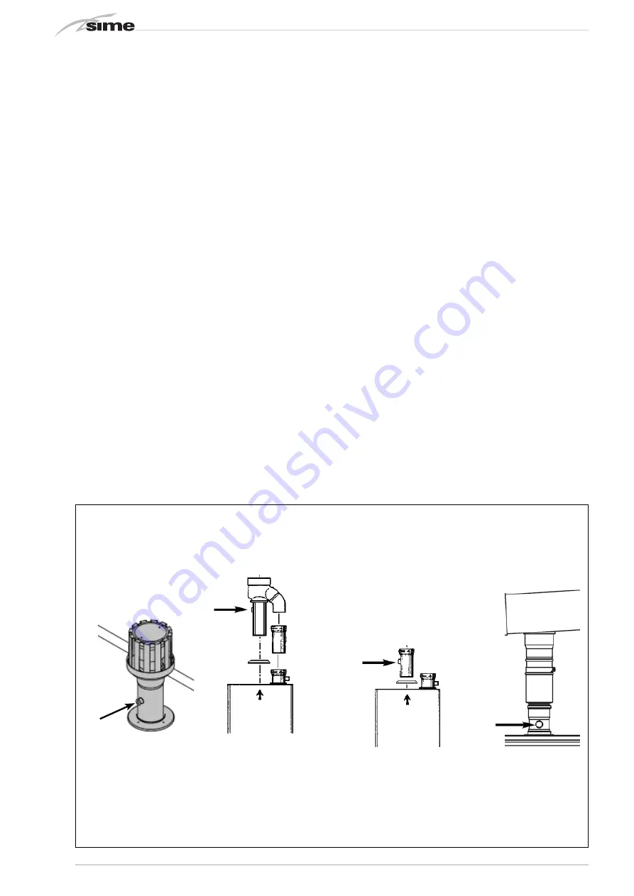
Connect the fl ue gas analyser to the
fl ue gas sampling point as shown in
the diagram.
Procedure for checking the combu-
stion.
Operate the boilers in “Chimney
Sweep “mode as described in sec-
tion 4.5.1 and record the measure-
ments from the fl ue gas analyser
on both minimum and maximum
output.
Compare the results to the fol-
lowing:
CO less than 200ppm
CO2 between 8.7% and 9.3% natural
gas, and 9.9% and 10.5% LPG
Ratio less than 0.004
If the combustion reading is grea-
ter than the acceptable value AND
the integrity of the complete fl ue
system, combustion circuit seals
have been verifi ed, AND the gas in-
let pressure has been verifi ed, AND
the boiler parameter settings are
correct, proceed as shown in 4.2.2
Any adjustments should be done in
small steps and adjustments of no
more than 1/8th of a turn should
be made, waiting at least 1 minute
between adjustments to allow the
settings to stabilise. Using the CO2
reading, adjustments should be
made to the “OFF-SET” screw (6 fi g
16) if it is incorrect at the minimum
output, or to the “SHUTTER” (5
fi g16) if it incorrect at the maximum
output.
If an acceptable setting level can-
not be achieved, re-confi rm that the
integrity of the fl ue system, combu-
stion circuit and working gas supply
pressure. If required contact HUNT
Heating for further assistance.
Fig. 15/a


