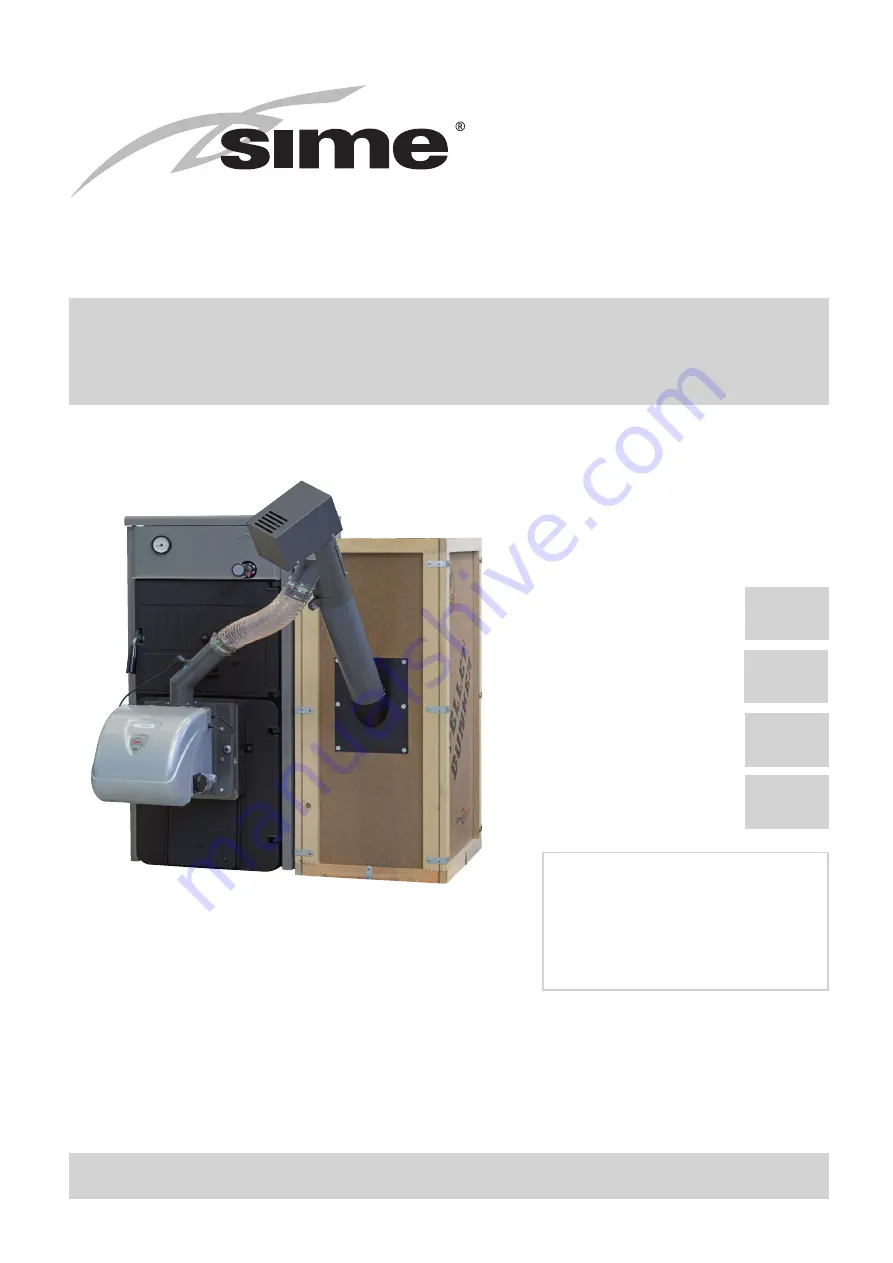
SOLIDA 5 PL
cod. 8058540
Kit pellet SOLIDA 5 PL
cod. 8075950
SOLIDA 8 PL +
cod. 8075742
Kit pellet SOLIDA 8 PL + cod. 8075960
SOLIDA 5 PL/8 PL+
Fonderie SIME SpA
Cod. 6113721A - 05/2016
IT
ENG
Page 1: ...SOLIDA 5 PL cod 8058540 Kit pellet SOLIDA 5 PL cod 8075950 SOLIDA 8 PL cod 8075742 Kit pellet SOLIDA 8 PL cod 8075960 SOLIDA 5 PL 8 PL Fonderie SIME SpA Cod 6113721A 05 2016 IT ENG ...
Page 2: ...co qualificato Per evitare il riflusso dell acqua dell impianto installare delle valvole di non ritorno o rubinetti che vanno aperti solo nel caso di reintegro d acqua nell impianto NOTE GENERALI L installazione dell apparecchio deve essere effettuata da personale professionalmente qualificato che operi in conformità alle norme nazionali vigenti ed alle indicazioni riportate nel manuale a corredo ...
Page 3: ...a potenza termica si riduce di circa il 10 1 1 DESCRIZIONE 1 1 1 INTRODUZIONE Le caldaie di ghisa SOLIDA PL sono una valida soluzione agli attuali problemi energetici in quanto adatte a funzionare con combustibili solidi legna e carbone Le caldaie SOLIDA PL sono conformi alla Direttiva PED 2014 68 UE 1 1 2 FORNITURA Le caldaie vengono fornite in due colli sepa rati Corpo caldaia assemblato correda...
Page 4: ...ma al la som mi tà di mi nui ta di 0 50 m per ogni cam bia men to di di re zio ne del con dot to di rac cor do tra cal daia e can na fu ma ria 1 00 m per ogni me tro di svi lup po oriz zon ta le del rac cor do stes so 1 2 3 ALLACCIAMENTO IMPIANTO È opportuno che i collegamenti siano facil mente disconnettibili a mezzo bocchettoni con raccordi girevoli È sempre consigliabile montare delle idonee sa...
Page 5: ...ianchi Il montaggio dei componenti del mantello va eseguito nel seguente modo fig 6 Svitare di alcuni giri il secondo o il terzo dado di ciascun tirante Agganciare il fianco sinistro 1 sul tirante inferiore e superiore della caldaia e rego lare la posizione del dado e controdado del tirante superiore Bloccare il fianco serrando i controdadi Per montare il fianco destro 2 procedere nella stessa man...
Page 6: ...a di 60 C dell acqua di caldaia fissare la catena sulla leva della serranda immissione aria facendo in modo che questa presenti una apertura di circa 1 mm A questo punto il regolatore risulta tarato ed è possibile scegliere la temperatura di lavoro desiderata ruotando la manopola Regolatore REGULUS RT2 Il campo di regolazione è compreso tra 30 e 90 C fig 8 Per il montaggio e la messa in funzione s...
Page 7: ...la bacinella di raccolta Per la pulizia dei passaggi fumo utilizzare un apposito scovolo fig 11 1 3 3 MANUTENZIONE Non effettuare alcuna operazione di manu tenzione smontaggio e rimozione senza prima aver scaricato correttamente la calda ia Le operazioni di scarico non devono effet tuarsi con temperature dell acqua elevate ATTENZIONE La valvola di sicurezza dell impianto deve essere verificata da ...
Page 8: ...1 2 CARATTERISTICHE TECNICHE Modello SOLIDA 5 PL SOLIDA 8 PL Potenza termica nominale kW 26 20 32 20 Potenza termica minima kW 7 84 8 98 Portata termica nominale kW 34 07 40 36 Portata termica minima kW 10 62 11 26 Rendimento utile massimo 76 90 79 78 Rendimento utile minimo 73 82 79 75 CO mg Nm3 al 10 di O2 a potenza termica nominale 516 01 103 21 CO mg Nm3 al 10 di O2 a potenza termica minima 77...
Page 9: ...e il nasello con relative viti di fissaggio Fig 13 Smontaggio flangia cieca Fig 14 Smontaggio griglia B Collocare il 1 deflettore in ghisa con i due distanziali posteriori Fig 15 Distanziale posteriore Fig 16 1 deflettore e distanziale posteriore C Collocare il 2 deflettore in ghisa con i due distanziali anteriori Fig 17 Distanziale anteriore Fig 18 2 deflettore e distanziale anteriore ...
Page 10: ...VELLE DI CEMENTO DEVONO ESSERE ADIACENTI ALLA PARTE ANTERIORE DELLA CALDAIA E Dopo il montaggio delle tavelle collocare l ultimo deflettore in ghisa Fig 21 Ultimo deflettore F Avvitare le viti M10 alla flangia G Fissare la flangia alla porta della camera di combustione con le 4 viti M8 interponendo la guarnizione Fig 22 Flangia Fig 23 Fissaggio della flangia alla porta camera di combu stione ...
Page 11: ...issaggio del bruciatore ATTENZIONE SERRARE I DADI FINO A QUANDO LA PIASTRA DEL BRUCIATORE NON SI APPOGGI ALLA FLANGIA DELLA CALDAIA NON STRINGERE OLTRE J Svitare il regolatore termostatico se previsto ed avvitare la riduzione in ottone con sigillante per la tenuta idraulica K Avvitare il termostato di sicurezza alla riduzione Fig 27 Riduzione in ottone Fig 28 Termostato di sicurezza _ ...
Page 12: ...9 Togliere il termometro Fig 30 Tappare il foro M Bloccare la portina aspirazione se in precedenza la caldaia era stata utilizzata per il funzionamento a legna o carbone Fig 31 Portina aspirazione ATTENZIONE APRIRE LA PORTA DI CARICAMENTO SOLO CON BRUCIATORE SPENTO ...
Page 13: ...1 tubo coclea 1 2 dado M8 10 3 flangia coclea 1 4 rondella M8 14 5 bullone M8x20 6 6 serbatoio 1 7 base serbatoio 2 8 bullone M8x30 4 Fig 32 Montaggio del contenitore pellet e della coclea NOTA Si consiglia di sostituire dopo l avviamento iniziale il con tenitore e la griglia di protezione fornita a corredo con un contenitore pellet omologato ...
Page 14: ... termostato di sicurezza Fig 33 Cavo motore coclea Fig 34 Connettore termostato di sicurezza C Posizionare la sonda di mandata 3 inserendola nella guaina posta sul corpo caldaia 4 Fig 35 Sonda mandata Fig 36 Sonda mandata D Collegare il cavo di alimentazione del bruciatore 5 alla rete elettrica BLU NEUTRO MARRONE FASE GIALLO VERDE TERRA Fig 37 Collegamento alla rete elettrica 1 2 5 3 4 ...
Page 15: ...a cura dell installatore FOTORESISTENZA FLUSSOSTATO SCAMBIATORE A PIASTRE TERMOSTATO SANITARIO BOLLITORE SCHEDINO IDRO CARICATORE PELLET VENTILATORE SPIRALE DI ACCENSIONE FUSIBILE 500 mA RIT 250 V SCHEDA PRINCIPALE OPZIONALI SPIA SIRENA ALLARME SPIA ALLARME IDRO VALVOLA DEVIATRICE 3 VIE POMPA Fig 38 ...
Page 16: ...16 t JF JD JC JB JA JE JG HI LIMIT 2 SONDA NTC CR TA TERMOSTATO DI SICUREZZA POSSIBILITÀ DI COLLEGAMENTO di un Termostato ambiente TA di un comando remoto ON OFF CR Fig 39 SCHEDA SECONDARIA ...
Page 17: ...i ritiene responsabile per eventuali danni a persone animali o cose causati da errori nella scelta dei componenti o nella realizzazione dell impianto Schema idraulico di principio che può essere utilizzato come una valida indicazione A B C D EAF E 1 2 4 5 5 5 5 5 5 5 5 5 5 5 6 8 10 11 12 13 9 7 4 LEGENDA A Caldaia a pellet B Puffer C Gruppo anticondensa D Riempimento e svuotamento caldaia impianto...
Page 18: ...252LH 502 ahs 220 240V AC 50 HZ 38W 3 Braciere 4 Griglia alloggio pellet rimovibile per la pulizia 5 Fotoresistenza vede la luminosità della fiamma 6 Bocca entrata pellet 7 Termostato di sicurezza pellet 8 Alimentazione elettrica 9 Connettore coclea 10 Scheda controllo bruciatore 11 Pannello Display 12 Adesivo Thermosticker bruciatore 13 Adesivo Thermosticker tubo alimentazio ne pellet Fig 40 2 4 ...
Page 19: ...ura del bruciatore può essere sintomo di un elevato deposito di cenere Una volta ripristinate le normali con dizioni di funzionamento il thermo sticker ritorna alla sua colorazione normale nero Il thermosticker bruciatore deve essere controllato regolarmente e comunque dopo qualsiasi procedu ra di manutenzione della caldaia e o bruciatore a pellet Il thermosticker indica un surriscal damento del t...
Page 20: ...i collegamento 2 4 6 ASSIEME CALDAIA E CONTENITORE PELLET Fig 45 Coclea Bruciatore Tubo flessibile autoestinguente Caldaia SOLIDA PL Pannello di controllo Alimentatore con motore coclea Contenitore del pellet da 80 kg Fissare il termostato di sicurezza pellet con la fascietta fornita a corredo AVVERTENZA Nell assemblaggio utilizzare il foro senza vernice per assicura re la messa a terra ...
Page 21: ...tiva SOLO PER UN NUMERO LIMITATO DI ORE è consentito l utilizzo di pellet che non rispetta la classe richiesta In questo caso il combustibile essendo di bassa qualità genererà un elevato residuo di ceneri che comporterà la necessità di una pulizia più frequente della griglia del bruciatore e delle pareti dello scambiatore di calore Categoria pellet Ad DU A Ad 0 6 DU 97 0 AB Ad 0 6 DU 97 0 B 0 6 Ad...
Page 22: ...tere calorifico MJ kg 16 5 16 5 Umidità 10 10 Polvere 13 1 3 Resistenza meccanica 97 5 4 97 5 4 Residuo in cenere 2 0 7 1 5 Temperatura di fusione della cenere C 1200 1100 Cloro 2 0 02 0 03 Zolfo 2 0 05 0 05 Azoto 2 0 3 0 5 Rame mg kg 2 10 10 Cromo mg kg 2 10 10 Arsenico mg kg 2 1 1 Cadmio mg kg 2 0 5 0 5 Mercurio mg kg 2 0 1 0 1 Piombo mg kg 2 10 10 Nichel mg kg 2 10 10 Zinco mg kg 2 100 100 1 no...
Page 23: ...di esso e di 4 pulsanti su cui è disegnato un cerchio bianco le cui funzioni sono di volta in volta descritte sul display accanto al tasto relativo 2 5 2 ACCENSIONE DEL PANNELLO 2 5 2 1 STARTUP PANNELLO SUCCESSIVO ALL IMPOSTAZIONE DEL TIPO CALDAIA Il display visualizza la schermata di Avvio Vedi Fig 48 Schermata AVVIO 2 5 2 2 STARTUP PANNELLO Ad ogni accensione successiva si visualizza sul display...
Page 24: ...lie Anomalie Tabella 4 Stringhe visualizzate nella schermata AVVIO Questo avviso viene visualizzato solo se l ECO è stato attivato e non sia stato inviato un comando di OFF da parte dell utente oppure sia stato inviato un comando di ON Questo avviso viene visualizzato solo se presente almeno un anomalia Tutte le schermate che saranno descritte successivamente mantengono la retroilluminazione al ma...
Page 25: ...la schermata di selezione Vedi Fig 51 nella quale è possibile variare il valore desiderato di 1 livello in un intervallo compreso tra 1 ed il valore massimo impostabile previsto dal modello della caldaia 3 9 e s c O k F i r e Fig 51 Schermata SET_POT Il valore sulla riga superiore è lampeggiante per indicare che è modificabile Alla pressione dei tasti Tasto 4 e Tasto 2 si ottiene un incremento dec...
Page 26: ...a Tabella 5 sono elencate le funzioni nell ordine in cui compaiono con i rispettivi valori modificabili Funzione Valore Temp Acqua Vedi 2 5 4 1 Data e Ora Vedi 2 5 4 2 Crono Vedi 2 5 4 3 Impostazioni Vedi 2 5 4 4 Menu Tecnico Vedi 2 5 4 5 Info Utente Vedi 2 5 4 6 Anomalie Vedi 2 5 4 7 Tabella 5 Elenco funzioni Menu Questa funzione è visibile solo se la caldaia è in ON o in ACCENSIONE Questa funzio...
Page 27: ...urazione impostata nei vari programmi quando abilitata nella schermata AVVIO si visualizzerà la scritta corrispondente come descritta nella Tabella 4 La funzione Azzeramento permette di cancellare le impostazioni dei programmi ripartendo dalla configurazione iniziale di default per fare ciò viene richiesta una conferma dell azione di azzeramento Le funzioni dei programmi sono un nuovo livello menu...
Page 28: ...ne la durata della luminosità nella schermata di AVVIO Impostando On il diplay rimar rà sempre acceso gli altri valori indicano dopo quanto la luminosità del dispaly passa al livello basso C F La funzione C F permette l impostazione dell unità di misura da utilizzare per la visualizzazione delle temperature all interno di tutte le schermate del pannello che lo prevedono L impostazione da fabbrica ...
Page 29: ... il pannello visualizza una schermata analoga a quella per il precaricamento del pellet Vedi Fig 53 Funzione precaricamento pellet Premendo esc Tasto 1 si torna alla schermata precedente mentre il tasto Ok Tasto 3 avvia la funzione e si visualizza la conferma della sua abilitazione L arresto della Pulizia del condotto di scarico dei fumi avviene con le stesse modalità della funzione Carica coclea ...
Page 30: ...re Percentuale 10 100 Menu Aria Combustione Controllo Giri On Off Portata P Min 0 400 lpm Portata P Max 0 400 lpm Giri P Min 300 2750 rpm Giri P Max 300 2750 rpm Tipo Motore 0 3 Menu Secondo Espulsore Abilitazione On Off Accensione 1 0 30 Accensione 2 0 30 Spegnimento 1 0 30 Spegnimento 2 0 30 Livello 1 0 30 Livello 5 0 30 Menu Idro Modalità Idro On Off Pressostato Acqua On Off Pressione Acqua Max...
Page 31: ...re cambiare in coerentemente con il tipo di dato e permettono di variare il parametro Premendo il tasto Ok Tasto 3 si conferma il valore e si torna alla visualizzazione precedente senza lampeggio Il tasto esc Tasto 3 permette anche esso di tornare alla schermata precedente ma senza confermare il valore La visualizzazione di tutte le voci del livello dei sottomenù e dei valori permane per 60s dopod...
Page 32: ... Ore Funzionamento 000000 999999 ore Ore Service 0000 9999 ore Assistenza numero di telefono Espulsore Fumi 0000 2500 rpm Temperatura Fumi 000 300 C Tempo Coclea 0 1 12 0 secondi Pressione Acqua 0 0 5 0 bar Tabella 13 Elenco voci menu Info Utente Il valore massimo visualizzabile dipende dal valore impostato gestito dalla scheda Visualizzato solo se la modalità idro ed il pressostato sono abilitati...
Page 33: ...omando di sblocco i n f o A L L A R M E A 0 1 M a n c a t a A c c e n s i o Fig 57 Schermata ALLARME Nella riga inferiore viene visualizzato a scorrimento il tipo di allarme con nome identificativo scritto per intero nella riga superiore invece si visualizza al centro la scritta ALLARME lampeggiante mentre la scritta info ed il codice di allarme Axx restano accesi fissi Premendo il tasto On Off Ta...
Page 34: ...oni per ripristino A01 Mancata accensione Pulire Braciere e Ritentare A02 Spegnimento fiamma Riempire Serbatoio Pellet A03 Surriscaldamento Serbatoio Pellet Controllare Libretto Istruzioni A04 Temperatura Fumi Eccessiva Controllare Libretto Istruzioni A05 Allarme Pressostato NON PREVISTO A06 Allarme Aria Combustione NON PREVISTO A07 Porta Aperta NON PRESENTE A08 Guasto Espulsore Fumi Chiamare Assi...
Page 35: ...ne automaticamente provocando lo spegnimento del brucia tore quando la temperatura in caldaia supera i 95 C Per riavviare la caldaia agire sul pulsan te come indicato in figura Nell operazine di riarmo si raccomanda di non togliere la staffa di protezione del termostato Se il fenomeno si ripresenta con una certa frequenza far controllare l appa recchio da personale qualificato 2 5 8 Manutenzione a...
Page 36: ...izioni di garanzia ne determina la nullità l Utente dovrà conservare la propria copia da esibire al Centro Assistenza Autorizzato in caso di necessità Nel caso in cui non sia stata effettuata la verifica iniziale dovrà esibire la documentazione fiscale rilasciata all acquisto dell appa recchio Per le caldaie a gasolio esclusi i gruppi termici le caldaie a legna carbone escluse le caldaie a pellet ...
Page 37: ... by qualified technical staff To avoid system water backflow install check valves or valves that are only opened to reintegrate water into the system GENERAL NOTES The appliance must be installed by professionally qualified personnel acting in compliance with national regula tions in force and instructions in the manual This appliance is not intended for use by persons including children whose phy...
Page 38: ... the blast gate damper a contact spring for the bulb of the thermometer and the M6 lever to be fixed at the blast gate damper Test cer tificate to be kept with the documents of the boiler Miscellaneous accessories required to use the boiler with pellets see Section 2 in the manual Cardboard box for casing with thermom eter and documents bag 1 1 3 DIMENSIONS 1 1 4 TECHNICAL FEATURES 1 1 5 HEAD LOSS...
Page 39: ...oning of the flue you should consider the effective height of the chimney in meters measured from the flame axis at the top diminished with 0 50 m for each direction chang ing of the connection tube between boiler and flue 1 00 m for each horizontal devel opment meter of the connection itself 1 2 3 CONNECTION OF THE PLANT The connections should be easily discon nected by means of pipelines with re...
Page 40: ...ok the left side 1 on the lower tie rod and superior of the boiler and adjust the position of the nut and locknut of the upper tie rod Fix the lateral side in blocking the lock nut In order to assembly the right side 2 proceed in the same way Hook the front upper board 3 intro ducing the two splines in the opening obtained on each side Carry out the same operation to fix the back lower board 4 The...
Page 41: ...hed in the boiler fix the chainlet in such a way on the lever of the air gate damper in order to obtain an opening of about 1 mm Now the regulator is calibrated and it is possible to choose the desired operating temperature by rotating the knob REGULUS RT2 Regulator The adjustment field is included between 30 and 90 C fig 8 Follow the same instructions of the Thermomat regulator for the assembly a...
Page 42: ...basin Use a proper pull through for the cleaning of the smoke passages fig 11 1 3 3 MAINTENANCE Do not perform any maintenance work dismantling or removal of parts without properly emptying the boiler first The boiler must not be emptied when the water is hot CAUTION The safety valve on the system must be inspected by technically qualified person nel in accordance with the laws of the country of d...
Page 43: ...2 1 1 OVERALL DIMENSIONS Fig 12 2 1 2 TECHNICAL FEATURES Model SOLIDA 5 PL SOLIDA 8 PL Nominal thermal output kW 26 20 32 20 Minimum thermal output kW 7 84 8 98 Nominal heat input kW 34 07 40 36 Minimum heat input kW 10 62 11 26 Maximum useful efficiency 76 90 79 78 Minimum useful efficiency 73 82 79 75 CO mg Nm3 at 10 of O2 at the nominal thermal input 516 01 103 21 CO mg Nm3 at 10 of O2 at the m...
Page 44: ... and latch with the relative screws Fig 13 Remove the blind plate Fig 14 Remove the grille B Place the cast iron deflector with the rear side supports 2 Fig 15 Rear side supports Fig 16 1st deflector with the rear side supports C Place the cast iron deflector with the front side supports 2 Fig 17 Front side supports Fig 18 2nd deflector with the front side supports ...
Page 45: ...nt bricks WARNING THE CEMENT BRICKS MUST BE ADJACENT TO THE FRONT PART OF THE BOILER E Place the last cast iron deflector Fig 21 Last cast iron deflector F Screw the M10 screws to the blind plate G Fix the plate to the combustion chamber door with the 4 M8 screws interposing the gasket Fig 22 Plate Fig 23 Plate fixed to the combustion chamber door ...
Page 46: ...bly Fig 26 Fixing of the burner WARNING TIGHTEN THE NUTS UNTIL THE BURNER PLATE RESTS ON THE BOILER PLATE DO NOT TIGHTEN TOO MUCH J Unscrew the thermostatic regulator if provided and screw the brass reduction by interposing the sealant for the hydraulic seal K Screw the safety thermostat to the reduction Fig 27 Brass reduction Fig 28 Safety thermostat _ ...
Page 47: ... the panel hole Fig 29 Remove the thermometer Fig 30 Plug the hole M Block the suction door if the boiler was previously used for operation with wood or carbon Fig 31 Suction door WARNING OPEN THE LOADING DOOR ONLY WHEN THE BURNER IS TURNED OFF ...
Page 48: ... with an approved pellet container N Assembly of an 80 kg tank ensure the container is fixed to the ground 6 4 5 1 2 2 7 3 4 8 Pos Description No 1 screw feeder tube 1 2 M8 nut 10 3 screw feeder ring 1 4 M8 washer 14 5 M8x20 bolt 6 6 tank 1 7 tank base 2 8 M8x30 bolt 4 Fig 32 Tank and screw feeder assembly ...
Page 49: ... coming from the burner to the safety thermostat Fig 33 Screw feeder motor cable Fig 34 Safety thermostat connector C Place the inlet joint 3 in the sheath 4 found on the boiler body Fig 35 Inlet joint Fig 36 Inlet joint D Connect the burner power cable 5 to the mains BLue NEUTRAL brown PHASE yellow green EARTH Fig 37 Connection to the mains 1 2 5 3 4 ...
Page 50: ... mA RIT 250 V SCHEDA PRINCIPALE OPZIONALI SPIA SIRENA ALLARME SPIA ALLARME IDRO VALVOLA DEVIATRICE 3 VIE POMPA PUMP OPTIONAL MAIN BOARD HYDRO BOARD 3 WAY DIVERTER VALVE HYDRO ALARM LIGHT WARNING LIGHT ALARM SIREN FLOW SWITCH PLATE HEAT EXCHANGER SANITARY THERMOSTAT CHAMBER PELLET LOADER VENTILATOR IGNITION COIL 230V 50Hz Electrical supply Connections to be made by the installer PHOTORESISTOR Fig 3...
Page 51: ...IT ENG 51 t JF JD JC JB JA JE JG HI LIMIT 2 NTC SENSOR SAFETY THERMOSTAT CR AT CONNECTION OPTION an ambient thermostat AT a remote control ON OFF CR SECONDARY BOARD Fig 39 ...
Page 52: ...k SIME cannot be held liable for harm to people or animals or damage to property attributable to an incorrect choice of components or improper set up of the system The hydraulic circuit diagram that can be used as a valid reference A B C D EAF E 1 2 4 5 5 5 5 5 5 5 5 5 5 5 6 8 10 11 12 13 9 7 4 LEGEND A Pellet heater B Puffer C Anti condensation unit D Filling and emptying of the water heater syst...
Page 53: ...A 8 PL RLG97 0042 A16 30252LH 502 ahs 220 240V AC 50 HZ 38W 3 Brazier 4 Pellet grille can be removed for cleaning 5 Photoresistor see the brightness of the flame 6 Pellet feed hole 7 Pellet safety thermostat 8 Power supply 9 Screw feeder connector 10 Burner control card 11 Display panel 12 Burner thermosticker 13 Pellet feed tube thermosticker Fig 40 2 4 2 DIMENSIONS Fig 41 ...
Page 54: ...ture of the burner may indicate a high ash deposit Once the normal operating condi tions are restored the thermosticker returns to its normal colour black The burner thermosticker must be checked on a regular basis and after any maintenance procedures carried out on the boiler and or burner oper ating with pellets The thermosticker indicates an over heating of the pellet feed tube The activation o...
Page 55: ...on 52 W Flexible connection tube 2 4 6 BOILER AND PELLET CONTAINER ASSEMBLY Fig 45 Screw feeder Burner Self extinguishing flexible tube SOLIDA PL boiler Control panel Power pack with screw feeder motor 80 kg pellet container WARNING During assembly use the hole without paint to assure grounding Fasten the pellet safety thermostat with the sup plied clamp ...
Page 56: ...ve ONLY FOR A LIMITED NUMBER OF HOURS it is possible to use pellets that do not comply with the requested class In this case the fuel being of lower quality will generate a high ash residue which will result in the need for more frequent cleaning of the burner grille and the heat exchanger walls Pellet category Ad DU A Ad 0 6 DU 97 0 AB Ad 0 6 DU 97 0 B 0 6 Ad 1 0 DU 97 0 BC 0 6 Ad 1 0 DU 97 0 C 1...
Page 57: ...alorific value MJ kg 16 5 16 5 Humidity 10 10 Dust 13 1 3 Mechanical resistance 97 5 4 97 5 4 Ash residue 2 0 7 1 5 Ash melting temperature C 1200 1100 Chlorine 2 0 02 0 03 Sulphur 2 0 05 0 05 Nitrogen 2 0 3 0 5 Copper mg kg 2 10 10 Chromium mg kg 2 10 10 Arsenic mg kg 2 1 1 Cadmium mg kg 2 0 5 0 5 Mercury mg kg 2 0 1 0 1 Lead mg kg 2 10 10 Nickel mg kg 2 10 10 Zinc mg kg 2 100 100 1 no more than ...
Page 58: ... on off button with the corresponding I O icon and 4 white circled keys whose function descriptions appear on the display close to each of them 2 5 2 POWERING UP THE SYSTEM 2 5 2 1 PANEL STARTUP AFTER CONTROLLED HEATER TYPE SETTING The display shows the Start screen See Fig 48 START screen 2 5 2 2 SYSTEM START UP When starting up the display shows a wait screen during this time the producer s logo...
Page 59: ...Active Alarm conditions active Alarms Table 4 Displayed strings in the START screen This notification is only displayed if the ECO option is on and no OFF command has been issued by the user or an ON command has been issued This notification is displayed only if at least one alarm condition is currently active For all the screens which will be described below the display backlighting will be maint...
Page 60: ...y holding the key pressed for 2s the selection screen will appear See Fig 51 from within this screen the value may be changed by1 level steps within an interval ranging from 1 to the maximum value which depends on the controlled heater model 3 9 e s c O k F i r e Fig 51 SET_POT screen The value on the top line flashes to let the user know that it may now be changed By pressing the buttons key 4 an...
Page 61: ...le 5 the various functions are listed in the same order as they appear on the display along with their values Function Value Water Temp See 2 5 4 1 Day and Time See 2 5 4 2 Chrono See 2 5 4 3 Settings See 2 5 4 4 Technical menu See 2 5 4 5 User Info See 2 5 4 6 Warnings See 2 5 4 7 Table 5 Menu functions list This function is visible only if the heater is ON or in IGNITION This function is visible...
Page 62: ...ed to set active the chrono operation mode on the basis of the currently defined weekly on off time pattern when active the relevant string is displayed in the START screen as described in Table 4 The option Reset Chrono is used to cancel all current settings which will be taken back to the default a confirmation is required to actually have the default values loaded The scheduling options may be ...
Page 63: ...cklighting option allows the user to set the time and the backlighting level used in the START screen Choosing On the display will then be kept lighted up all the time the other items set the time when the backlighting is dimmed down C F The C F option allows the user to select the measuring unit to be used for any temperature value displayed The default setting is Auto such setting chooses the me...
Page 64: ... the auger feeder with pellet See Fig 53 Pellet feeder filling function By pressing esc key 1 the display reverts back to the previous screen while the key Ok key 3 starts the function showing the confirmation Stopping the burner cleaning function is gotten in the same way as for the pellet filling function by pressing again the key 3 PUMP ACTIVATION The option pump activation option Start pump sh...
Page 65: ... lpm Airflow at Max Power 0 400 lpm RPM Min Power 300 2750 rpm RPM Max Power 300 2750 rpm Motor Type 0 3 Second Extractor Menu Enable On Off Ignition 1 0 30 Ignition 2 0 30 Shut down 1 0 30 Shut down 2 0 30 Level 1 0 30 Level 5 0 30 Hydro Menu Hydro Mode On Off Water Pressostat On Off Max Water Pression 2 5 4 7 Bar Accumulator water storing tank On Off Modulating Pump on off temp dependent timed m...
Page 66: ...ws or may also change in depending on the displayed data type and they are used to increase or decrease the item value By pressing the button Ok key 3 the new value is confirmed and the display reverts to the previ ous screen unflashing The display will return to the previous screen without confirming the new value by pressing the esc key key 3 Each submenu item and its value stay displayed for 60...
Page 67: ...9999 hours Service Time 0000 9999 hours Service phone number Fumes Extractor exhauster fan 0000 2500 rpm Fumes Temperature 000 300 C Pellet Feeder Time 0 1 12 0 seconds Water pressure 0 0 5 0 bar Table 13 User Info menu items list The maximum value which can be displayed depends on the set value Displayed only if hydro mode and the water pressure switch option are enabled See 2 5 4 5 Hydro Menu HI...
Page 68: ...not be changed before issuing an unblock command i n f o A L A R M A 0 1 I g n i t i o n F a i l e d Fig 57 ALARM screen On the bottom line the alarm type and name is scrolled and in the middle of the top line ALARM blinks while info and the alarm code Axx are steady on The alarm notifying sound may be stopped by pressing the key On Off key 5 if the key is pressed for more than 2s the alarm will b...
Page 69: ... how to reset them Code Alarm type Informations A01 Ignition Failed Clean Brazier and Restart A02 Flame Shut Down Fill Pellet Tank A03 Pellet Tank Over Temperature See instruction manual A04 Fumes Over Temperature See instruction manual A05 Fumes Pressure Switch Alarm NOT EXPECTED A06 Combustion Airflow Alarm NOT EXPECTED A07 Door Open NOT PRESENT A08 Fumes Extractor Error Call Assistance A09 Fume...
Page 70: ...matically switching off the burner when the water heater tem perature exceeds 95 C To start the water heater back up again press the button as shown in the figure During the resetting procedure one must not remove the bracket that protects the thermostat If this event occurs frequently have qualified staff inspect the equipment 2 5 8 ANNUAL MAINTENANCE For optimum performance it is advis able to h...
Page 71: ......
Page 72: ...Fonderie Sime S p A Via Garbo 27 37045 Legnago VR Italia Tel 39 0442 631111 Fax 39 0442 631291 www sime it info sime it Solida PL ...