26
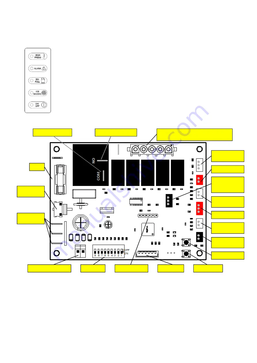
COMPONENT DESCRIPTION
1.
Front Console Panel
SVD SERIES
2.P.C. Board (As above picture)
Located in the control box, this board is the
brain of the system as it governs the ice
machine cyclematic through sensors, relays
and switches. It consists of two separated
printed circuits one at high and the other at low
voltage integrated with a fuse, of seven
connectors for the sensors/switches (as above
picture, of one outlet connector (front LED
display), of one serial port connector, oftwo2-
PIN plug for transformer input and output power,
of two terminals for input power live line and
compressor output, of 3 terminals for power null
line, of one 5-PIN plug for components output,
1
2
3
4
5
LEDNo.1
Alarm high pressure
LEDNo.2
Alarm
LEDNo.3
Bin full.
LEDNo.4
Operation
LEDNo.5
Electrical power supply
Water inlet valve & Water pump & Water
purge valve & Harvest valve & Fan motor
Startup delay
switch
(1008 only)
Condenser
sensor
Bin full sensor
Water level
sensor
Hi-
press.controller
MODE button
Ice thickness
sensor
Factory use only
CLEAN button
LED display
DIP Switch
Transformersecondary
Power in
(Null line)
Transformer
primary
Fuse
Power in (liver line)
Compressor contactor
Serial connector