background image

25

ht5000HB - pro5dl

2  S-VIDEO 

5  GRAPHICS RGB

3  COMPONENT 

1  VIDEO

1

2

3

5

S-VIDEO 3

GRAPHICS 1

COMPONENT 1

VIDEO 1

4  COMPONENT 

4

COMPONENT 2

6  GRAPHICS RGB

6

GRAPHICS 2

7  DVI

7

DVI

Source List / Rename Source 


1/1

9  HDMI 

12  HDMI 

10  HDMI 

8  HDMI

8
9

10

12

HDMI 2 

HDMI 5 

HDMI 3 

HDMI 1

11  HDMI 

11

HDMI 4 

13  HDMI 

13

HDMI 6 

14  SDI

14

SDI

Source List / Rename Source 


2/2

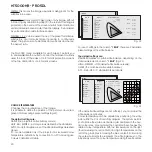
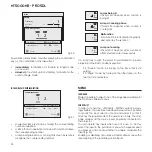
Active video signal sources (shown in the input selection menu) 
are ticked.
It may be useful to identify the input with a user defined name 
rather than the type of signal (for example, with the name of 
the connected device).
When you have decided to display an input, select NAME in the 
pull-down menu and rename the source currently in use. 
This makes it easier to remember which source is connected to 
a given input; you can use up to 12 alphanumeric characters 
for the name (for further details, see ENTERING TEXT).

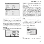
Entering text

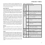
The text entry menu shown in Fig. 33 makes it possible to enter 
text quickly and easily.

Cancel

Confirm

Rename Source

 ()?@

1

 ABC

2

 DEF

3

GHI

4

 JKL

5

MNO

6

PQRS

7

-

+

 TUV

8


0

WXYZ

9

_ _ _ _ _ _ _ _ _ _ _

Fig.32

Text input mode is the same whether you are editing an exist-

ing name or entering a name for the first time. Characters can 

be entered in any of the available positions (represented by 
horizontal lines). Use the

 ◀

 and 

▶ 

keys to move the cursor left 

or right respectively.
Press the number key corresponding to the character; pressing 
once selects the first character, twice, the second character 
and so forth. The available characters are shown in the text entry 
menu that appears in this setup mode. Once you have entered 
a character, move to the next space on the right to enter the 
next  with  the 

  key  on  the  remote  control,  and  repeat  the 

procedure. This applies even if the letter is associated with the 
same key as before. Use the 

 key to switch from upper case 

to lower case characters and vice versa. Cancel errors with 


after selecting the character to be cancelled. Once you have 
completed the text entry procedure confirm your text and save 
it by pressing the MENU+ key on the remote control.If you wish to 
cancel the changes, press MENU- on the remote control.

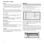
f1-f2 KEYS

The remote control is equipped with two keys (F1 and F2) which 
are associated with various different functions.
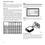
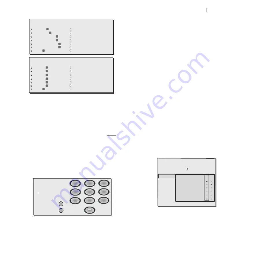
The screen shows six options, one for each line, and two col-
umns indicating the keys F1-F2. You can select F1 and F2 with 
the 

 and 

 keys on the remote control; select the function to 

assign to F1 or F2 with the 

▼ 

and 

 keys

The function performed by the key is indicated by the dot at 
the line-column intersection (Fig.34).
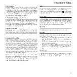
The six menu items are described below.

focus

Once  selected,  the  keys 

◀ 

and 

  allow  the  image  to  be 

focused.

Fig.34

Fig.33

Source List

F1/F2 Keys

Source Info

OSD Backgro

OSD Position

OSD Timeout

Linguage

Menu

English

Zoom

Focus

Magnification

Blank

Gamma Correction
Color temperature

F1

Summary of Contents for HT5000HB

Page 1: ...HT5000HB PRO5DL user and installation manual 460637000 ...

Page 2: ...p Down arrows open the quick menus MENU Switches on the On Screen Display and browses through its pages MEMORIES Activate the memory management menu INFO Displays information on the selected source and projector status ASPECT Selects the image Aspect ratio INPUT Displays input selection menu Places the projector in standby mode MENU Opens the On Screen Display menus and permits browsing though the...

Page 3: ...ite Video inputs 1 S Video inputs 2 Component or RGB inputs 4 RCA connectors and 5 BNC connec tors 2 graphic RGB inputs 6 HDMI inputs 1 SDI input 1 DVI D input allow it to be connected to a wide range of analogue and digital sources DVD players video recorders satellite and terrestrial receivers computers video game consoles camcorders etc Its image processing system permits optimum reproduction o...

Page 4: ... Multimedia provides the following information regarding the disposal and re cycling of the product Waste electrical and electronic materials WEE should never be disposed of in normal urban waste disposal facilities The label on the product shown here indicating a cancelled garbage can is intended to remind you that the product requires special handling at the end of its service life Materials suc...

Page 5: ... plug not the cable to disconnect the unit from the mains 1 Projection objective lens 2 Door for changing lens 3 Front receiver for infrared remote control 4 Objective lens release hole 5 Height adjustable support feet 6 Ventilation grille for air intake 7 Access compartment for changing bulb 8 Connection panel 9 Ventilation grille for air outlet 10 Ventilation grille for air outlet Use only the s...

Page 6: ... poorly ventilated areas as this may prevent sufficient cooling Never look directly at the projection lamp Never look directly at the objective lens when it is on as the intense light may damage your eyes Take particular care that children cannot do so Take special care regarding movement of the lens Do not place objects in the slots on the side of the lens and also ensure that horizontal and vert...

Page 7: ...r remote control Four 1 5V AAA type batteries for the remote control network cables for the projector instruction booklet If any of the accessories are missing please contact your dealer as soon as possible Instuction s manual Remote Control 4 Batteries AAA 1 5V Power Cables Projector 1 2 Extract the cardboard structure that contains the instructions manual and the connection cables Lift the proje...

Page 8: ...ge with the base of the projection screen Fig 2 Fig 2 Placed the projector at the desired distance from the screen the size of the projected image depends upon the distance between the lens and the screen and the zoom setting Use the motorized zoom Fig 3 widen or to narrow the pro jected image Use the motorized focus Fig 3 to obtain the best definition of the projected image If the focus is correc...

Page 9: ...projector is in standby status You can also use black motorized hideaway curtains to mark off the projection screen when you change the format of the projected image Fig 7 The activation command can be provided using output TRIG2 located on the back of the projector TRIG 1 TRIG 2 For rear installations a suitable translucid screen must be used For front installations it is advisable to use a scree...

Page 10: ...n starting from standby the lamp comes on After a short warm up the image appears blue light on The projected image comes from the input selected at the time of the last shutdown Fig 10 If too little time has elapsed since the last shutdown the lamp may not light if it is too hot In this case you should let the lamp cool off for a few min utes Shutdown and return to standby status From the remote ...

Page 11: ...pt the signals and degrade the quality of the projected image Conserve and use the cables with care Follow these simple instructions With the exception of RCA type coaxial connectors always check the correct direction of insertion of the connectors in their sockets to prevent deformation of the feet When you unplug equipment do not pull on the cables Do not twist or crush the cables For temporary ...

Page 12: ...Video recorder Video game console Television receiver HDTV receiver DVD player Video recorder Video game console Blue Ray player HD DVD player Computer 6 LINE INPUT 110 240 7 6 3 4 A FUSE T10A H 250V 14 Professional and broadcasting equipment 7 HDTV receiver DVD player Computer HDTV receiver DVD player Video game console Blue Ray player HD DVD player 8 9 10 11 12 13 ...

Page 13: ...t The output connector on the external appliance is normally coloured yellow and will often be labelled VIDEO Other signal and socket formats may be preferable because they give better image quality but this type of output socket is still the most commonly used and nearly all television receivers video recorders DVD players and camcorders etc use it S VIDEO Fit a mini DIN connector with an S Video...

Page 14: ...The system is delivered with default factory settings in which the dynamic IP address DHCP is active If the network to which the projector is connected has no DHCP server the current IP address displayed on screen may not be valid RS232 interface connector or USBinterface I 0 CONTROL USB CONTROL RS232 You can control a projector from a PC by connecting to this connector a cable from an RS232 seria...

Page 15: ...up wait for completion of the save procedure IP Address Mode Web interface Remote Control IP Address 172 031 127 055 Subnet Mask 255 255 000 000 Gateway 172 031 045 115 DHCP Host Name sim2prj Port 08080 Password XXXX Port 1 10001 Port 2 30704 Static IP Dinamico IP DHCP Apply Settings Factory Settings RESTORING SETTINGS To restore the projector s network setting to the default factory setting click...

Page 16: ...Temperature too high Error Code 2 Lamp error Error Code 3 Communication error Error Codes 4 e 5 Email sender CCCCCCCCCCCCCCCCCCCExxx C serial code of the projector sending the notification X error code Email subject WWWWWLLLLLFFFFFFXXXYYY W Total hours of projector use L Hours projector lamp on F Software firmware version X Operating status 0 OFF 1 ON 2 Lamp preheating 3 Lamp switching back on 4 L...

Page 17: ...aspect and the current user memory can be displayed by pressing the number key on the remote control corresponding to the selected source In the SETUP menu you can select whether or not to display this information for further information see SOURCE INFORMATION in the MENU section MAIN MENU Press the MENU key on the keypad or the MENU or MENU key on the remote control to access the main menu of the...

Page 18: ...ent use skin tones or a test card image with colour bars as a refer ence Sharpness This adjustment serves to modulate the signal to increase or decrease the level of picture detail When the sharpness value is reduced the image details ap pear less pronounced while increasing the value raises image definition making the outline of objects sharper Note that an excessively high value may result in a ...

Page 19: ...t of the displayed image There are six default aspects available and three user aspects with user settable parameters You can select a different aspect for each source the selected aspect ratio will be automatically applied the next time the relative source is displayed You can also select the required aspect ratio from the remote control by repeatedly pressing the key or by pressing the key and o...

Page 20: ...and or vertical dimensions are smaller than the display it is bordered by vertical and or horizontal black bands Personal 1 2 3 can be used if none of the preset formats are satisfactory User formulas make it possible to continuously adjust the picture size horizontally and vertically and hence the aspect ratio The PULL DOWN menu available for each aspect permits you to enable disable the outlet t...

Page 21: ...easant and well contrasted images OVERSCAN Eliminates irregularities around the outer borders of the im age Some less accurate sources may produce an image with uneven borders thanks to the overscan function these imperfections can be moved outside the projected area Position Use this adjustment to position the image vertically and hori zontally These parameters do not normally require adjustment ...

Page 22: ... or AUTO on the keypad If the automatic pro cedure fails to achieve the required effect enter the frequency and phase values manually and move sufficiently close to the screen to observe the effects of the adjustments SETUP This menu includes the less frequently used adjustments which may be helpful during installation for example the selection of the language for the On Screen Display or the disp...

Page 23: ... STANDBY mode the projector remains in STANDBY mode and awaits the power up command from the remote control or keypad TEST PATTERNS Displays a series of five test patterns which are useful when installing the system and checking basic functions Use the and keys to select the various test patterns Fig 28 Fig 27 INITIAL SETTINGS Resets the projector to its initial factory settings except Position Or...

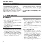
Page 24: ...fy the input selection menu and adapt it so that it matches the requirements of the user more closely The main page displays all the source inputs physically connected to the projector You can delete any inputs which are not in use To do this select the input in the pull down menu which appears when you press and choose whether to enable or disable the input Fig 32 Enabling or disabling of sources...

Page 25: ...t or right respectively Press the number key corresponding to the character pressing once selects the first character twice the second character and so forth The available characters are shown in the text entry menu that appears in this setup mode Once you have entered a character move to the next space on the right to enter the next with the key on the remote control and repeat the procedure This...

Page 26: ... as the key is pressed an OSD message lasting a few seconds confirms that the function has been activated You can restore the previous conditions by pressing any key on the remote control Gamma correction Successive pressing of the key in question F1 or F2 makes it possible to select any of the available gamma curves SOURCE INFORMATION When enabled YES each time the source is changed informa tion ...

Page 27: ...xt time it appears in fact the temporary memory will contain new information that takes account of any Memories selected on the last time but one that the MEMORIES page was accessed Memory 0 can be used even when you do not wish to enable Memories management for the signal in use In fact once Memory 0 has been selected when a source is chosen the settings that were effective at the time the Memory...

Page 28: ...ut sources Check the state of the connection by interpreting the code displayed by the projector LEDs Make sure the cooling air vents on the units are not blocked and that the room temperature is below 35 C Image is disturbed unstable or noisy Check compatibility of the video or graphic signals with the technical specifications of the projector and specifically with the specifications of the selec...

Page 29: ... menu Image too dark pale or unnaturally coloured Check compatibility of the video or graphic signals with the technical specifications of the projector and in particular with the specifications of the selected input Adjust the Contrast Brightness Colour and Tint parameters in the PICTURE menu If necessary adjust Colour Temperature and Gamma Correc tion IMAGE menu Graphic image with poor quality v...

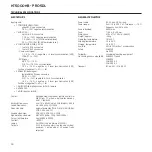
Page 30: ...nput panel remote control via RS232 from PC or home automation devices USB 1 1 LAN RJ45 Horizontal frequency from 15 to 80 kHz up to UXGA format 65 Hz Vertical frequency 48 100 Hz 24Hz 1080p Video standard automatic selection PAL B G H I M N 60 SECAM NTSC 3 58 and 4 43 Graphic standards VGA SVGA XGA SXGA UXGA High definition standard ATSC HDTV 480p 720p 1080i 1080p Colour temperature from 5500K to...

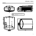
Page 31: ...31 ht5000HB pro5dl DIMENSIONS The specified length is with standard lenses installed ...

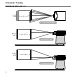
Page 32: ...32 ht5000HB pro5dl HORIZONTAL AND VERTICAL SHIFT TILT Screen height 30 Vertical Shift 15 Orizontal Shift 70 Vertical Shift Screen Center 0 Screen Center 0 Screen Center 0 Screen width Screen height ...

Page 33: ... 5 15 18 8 24 0 25 2 34 6 34 6 45 0 56 2 80 0 Throw Distance Throw FWA Fixed Wide Angle Throw Distance Image Width Lens Type FWA 1 FWA 2 Short Med short Med long Long Throw Ratio 0 67 1 1 12 1 1 39 1 87 1 1 87 2 56 1 2 56 4 16 1 4 16 6 96 1 Throw Distance feet Image Width Fixed Fixed Min Max Min Max Min Max Min Max feet 5 3 3 5 6 7 9 4 9 4 12 8 12 8 20 8 20 8 34 8 10 6 7 11 2 13 9 18 7 18 7 25 6 2...

Page 34: ...ble for any damage which may be caused directly or indirectly to persons pets or property due to failure to comply with all of the provisions of the instructions booklet especially warning concerning installation use and maintenance of the unit The manu facturer shall not be held liable for direct and or indirect damage caused by or resulting from use of the unit 6 For units for which call out ser...

Page 35: ...2998 www sim2usa com e mail sales sim2usa com SIM2 Deutschland GmbH Arndtstrasse 34 36 D 60325 Frankfurt Am Main Phone 0800 800 7462 Germany only Int Phone 49 163 500 7462 Fax 0800 900 7462 www sim2 de e mail info sim2 de Steinway House Worth Farm Little Horsted Nr Uckfield East Sussex TN22 5TT Phone 44 0182 5 750850 Fax 44 0182 5 750851 www sim2 co uk e mail info sim2 co uk Producer Registration ...

Reviews: