Operation
9
Attaching to the Tractor
Silvan Super Series 400 litre linkage sprayers are
equipped to fit tractors with either Category 1 or 2
linkages. The 600L, 800L & 1100L fit Cat 2 only.
On the 400 litre the inner end of each lower
linkage pin is Category 1 and the outer end is
Category 2. The lower holes in the top connection
plates are Category 1 and the upper holes are
Category 2.
Remove the PTO shaft from the sprayer by
depressing the locking pin. Lower the tractor
linkage
and attach it to the sprayer’s lower hitch
pins of the appropriate category, then connect the
top link using
the tractor’s top link pin. Secure the
linkage arms and top link pin with the tractors
lynch pins. Raise the tractor linkage to the desired
spraying height and level the sprayer by adjusting
the length of the top link and by using the lower
arm levelling mechanism.
Clean and grease the splines on the tractor and
sprayer PTO stub shafts and install the PTO shaft
making sure that the spring-loaded locking pins
engage in the interference grooves of both stub
shafts. Ensure that the PTO shaft guard chains,
if fitted, are attached to the sprayer and tractor.
PTO Shaft Length (Refer to instruction
booklet INS42 attached to PTO shaft)
Note: Upon delivery of a new PTO driven sprayer,
it is the selling dealer’s responsibility to install and
set the PTO driveshaft to the correct length, as
part of the installation service. The following
information is provided for reference.
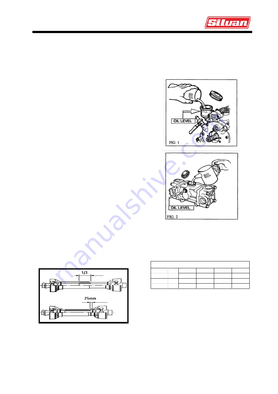
Set the linkage height so that the ends of the two
shafts are at their closest distance. Install the
PTO shaft making sure that there is at least
25mm of telescopic travel remaining between the
male and female sections. Raise and lower the
sprayer to check that the telescopic tubes of the
PTO overlap by approximately 1/3rd of their
length, and not less than 150mm, in all operating
positions.
Min 150mm
Min 150mm
If the PTO shaft must be shortened, cut equal
amounts from both male and female shafts and
safety covers. Carefully remove all burrs then
clean and lubricate before reassembling.
Pump
1. Check the oil level while the pump is standing
still and sitting horizontally. The oil must reach the
level indicated on the sight glass (BP75/20,
BP125/20 fig 1) or be visible on the oil level plug
(BP60/20 fig 2). Top up with SAE20W/40 oil if
necessary.
2. Adjust the air pressure in the pressure
accumulator if fitted in accordance with the
operating pressure used to spray. Adjust
according to Table A. The pressure can be
measured using a reliable bicycle fork pressure
gauge.(Note a car tyre or bicycle tyre gauge lets
too much air escape to be accurate).
Alternatively add air to the accumulator, to just
above the required pressure (using a car tyre
inflator is OK) start the pump and adjust the
pressure regulator to the required pressure then
bleed air from the accumulator until the
pulsations of the pump are least noticable, at
this point the needle on the pressure gauge will
be at its steadiest.
Spraying Bar
2-5
5-10
10-20
20-50
pressure p.s.i.
29-73
73-145
145-290 290-725
Surge air Bar
2
2-5
5-7
7
pressure p.s.i.
29
29-73
73-102
102
TABLE A


