


Communication via
CAN bus (CANopen)
MSA501
Date: 12.10.2018
Art. No. 88734
Mod. status 330/18
Page 10 of 51
4.3
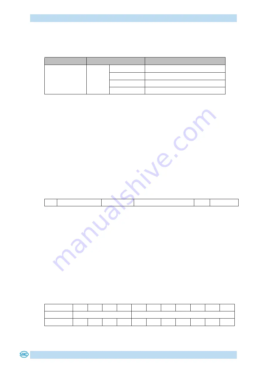
Reset to factory settings
To return to the original condition of the device as delivered, there exist the following
options:
Access
Coding
Settings are restored for
1011h
"load"
Sub-index 1
All parameters
Sub-index 2
Only bus parameters
Sub-index 3
Only CiA DS-406 parameters
Sub-index 4
Only manufacturer-specific parameters
Table 8: Access to factory settings
5
Communication via CAN bus (CANopen)
The CANopen communication profile CiA DS-301 V4.2, the Device profile for Encoders CiA DS-
406 V3.2 as well as the indicator specification CiA DS-303 Part 3 V1.4.0 for CAN diagnosis
form the basis for the MSA501 CAN. The MSA501 supports device class C1 and partly C2. The
details required for a better understanding of the operation are included in this
documentation. If more in-depth information is required, we recommend the applicable
technical literature on CAN or CANopen.
5.1
Telegram structure
The data telegram of a CAN message consists of the following fields:
SOF Identifier (COB-ID) Control field: Data field (max. 8 byte)
CRC
ACK/EOF
SOF:
(Start of Frame) start bit of the telegram
Identifier (COB-ID):
By means of the identifier, all bus subscribers check whether the message is relevant for
each of them.
The identifier determines the priority of the message. The lower the value of the identifier,
the higher is the priority of the message This enables preferential transmission of
important messages via the bus.
The Identifier field contains the identifier as well as bits for the recognition of the length of
the identifiers (11 or 29 bits). The device address, channel selection as well as data direction
are determined via the identifier as well.
Thus, the 11bit identifier (COB identifier) consists of a 4bit function code and a 7bit node
number.
Bit no.
10
9
8
7
6
5
4
3
2
1
0
Type
Functional code
Node number (Node ID)
Assignment x
x
x
x
0
0
x
x
x
x
X


