11
CUTTER ADJUSTMENTS
When the strap cutter begins to wear or
strapping seems difficult to cut off the strap
cutter may need adjustment. Contact the
Signode tool repair center or your Signode
representative for information on accessing
the adjustment screw.
Before attempting to adjust the cutter, first
place a single layer of strapping in the tool
and pull the weld handle to the full back
position.
Adjust the cutter blade position by turning
the adjustment screw inward (clockwise) or
out (counter-clockwise) using 1/8 turn
increments. Adjust the cutter blade so that
the cutting edge of the blade places a slight
impression into the single layer of strap.
Remove the
single layer of
strap. Run one
or more tool
cycles and
continue to
adjust the
cutter as
necessary until
proper strap
cut-off has
been obtained.
NOTE: Do not over tighten cutter mechanism
as lower strap damage or poor strap cut-off
will occur.
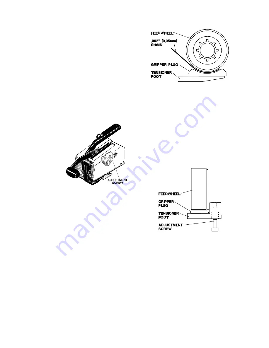
FEEDWHEEL TO GRIPPER PLUG
The feedwheel to gripper plug clearance may
require readjustment if the feedwheel,
tensioner foot or gripper plug has been
replaced. The feedwheel clearance should
also be inspected during routine tool
maintenance procedures. Adjust the
feedwheel clearance as follows:
1. Open the tensioner foot and place 1 to 2
layers of .002", 1/2" wide (.05 x 12mm)
shim stock between the feedwheel and
the gripper plug.
NOTE: Using a single .004" (.10mm) shim is
not recommended because a single thicker
shim may not conform to the feedwheel
shape, resulting in inaccurate clearance
measurements.
2. Release the tensioner foot to pinch the
shims between the feedwheel and the
gripper plug. Holding the shims with one
hand, jog the air motor on and off to
rotate the feedwheel at least one full
revolution. If properly adjusted the tool
should lightly tug at the shims while
rotating. Clearance between the
feedwheel and gripper plug at this point
should fall between .002"-.004" (.05-
.10mm).
3. If the feedwheel needs to be adjusted,
use a 3/32" hex wrench to rotate the
adjustment screw located in the
tensioner foot.
Turn the adjustment screw clockwise for
greater clearance and counter-clockwise
for less clearance. Turn the adjustment
screw only in 1/8 turn increments. After
each 1/8 turn, repeat the adjustment
testing as described in step 2.
4. Once the proper clearance has been
found the tool can be returned to service.
NOTE: Never turn out the adjustment screw
more than 1/8 turn at a time without testing
or completely removing the adjustment
screw. These actions will severely damage
both the feedwheel and gripper plug.
Summary of Contents for TENSION-WELD VXL-2000-Z
Page 1: ...VXL 2000 Z and VXM 2000 Z TENSION WELD STRAPPING TOOLS...
Page 29: ...29...
Page 38: ...38...


