


.
75.
The stabilizer is now be glued in place to the fuselage (for a little working time, we suggest 5-minute epoxy for this step).
Apply a thin layer of glue to the fuselage stab mount (FSM) and also to the leading edge of the stab, where it contacts F-7.
Position the stab in place, lining up the lines on its bottom side with the fuselage sides. Pin or use weights to hold it
perfectly flat to the fuselage. Now back away a few paces and sight directly at the rear of the model. Is the stab tilting left
or right compared to the wing panels? If so, use a little masking tape to hold it in the correct position and allow the glue to
cure.
76.
Glue the vertical fin in place to the top of the stab and the back of F-7, with the
tailpost glued into the fuselage, between the sides (we suggest 5-minute epoxy
for this step). Trial fit the fin in place and trim as required to achieve a perfect fit.
Apply a thin layer of glue to the bottom of the fin and its lower leading edge,
where it contacts F-7. Also apply glue to the sides and bottom end of the tailpost -
not too much. Position the fin in place onto the stab and into the fuselage - wipe
off any excess glue with acetone. Visually align the leading edge of the fin with
the center of the 1/4" balsa spine/stringer in front of it and pin in place. Use a 90
deg. triangle to position the fin at right angles to the stab and use tape to hold the
fin in position. Allow the glue to cure and remove the wing panels from the
fuselage.
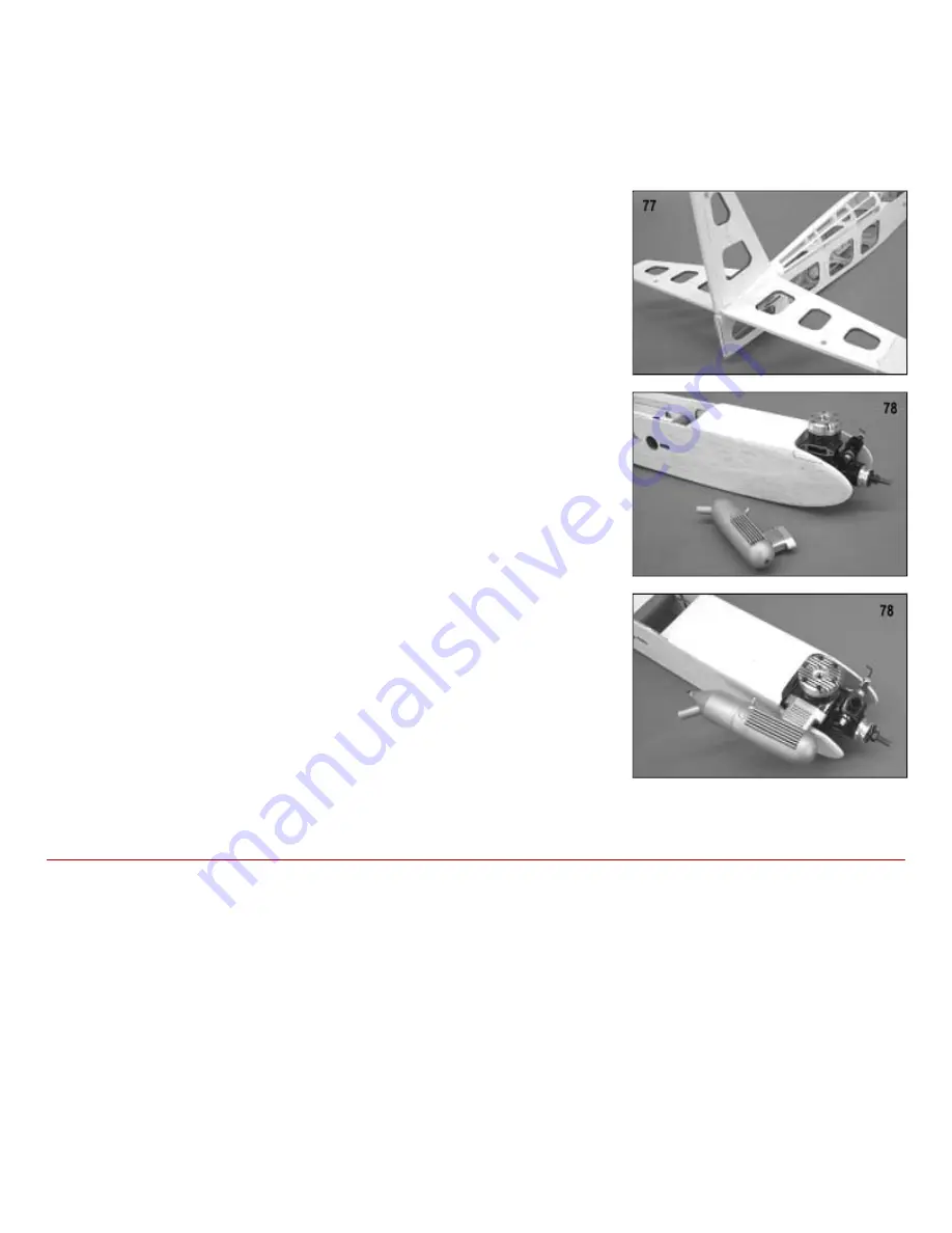
77.
Before gluing the left and right fin fairing blocks in place, use a single edge razor
blade to carefully notch the fin tailpost to clear the elevator joiner wire. This notch
should be cut to the trailing edge of the stablizer and 1/4" width. Once satisfied,
glue the fin fairing blocks in place to the fin, stab and back of F-7. Use a small
sanding block with 220 grit sandpaper to blend the fairing blocks smoothly to the
contours of F-7.
78.
Use the 6-32 x3/4" bolts provided to attach the two motor mount arms to the
firewall. Without the muffler installed, place your engine onto the motor mounts
and locate it to the previously drilled holes with at least two of 6-32 x1" bolts
(without nuts). You will likely note that in order for your engine to fit in place with
the muffler attached, the right fuselage side must first be trimmed to accept the
manifold. We suggest about 1/8" clearance from the manifold. Use a pencil and a
short straight edge to mark the fuselage side for trimming. Remove your engine
and trim away the fuselage side as required. Mount the muffler to the engine and
place it back on the mounts to check the clearance.
Some of the later two-stroke engines, with rear mounted remote needle valves,
may require a hole in the left fuselage side for clearance. If your engine has this
configuration, measure and drill the required hole. When these two issues have
been taken care of, lightly sand these areas for covering.
COVERING
The SOMETHIN EXTRA really lends itself to a wide variety of color schemes. You may even want to cover yours in a
scale color scheme as used on one of the many full-size Extra aircraft. Whatever the colors you choose for your model,
remember that you will really appreciate a strongly contrasting scheme, in order to keep good visual reference on the
model during extreme maneuvers.
To minimize weight and enjoy the full potential of this model, it should be covered in a good quality, light-weight iron-on
film, such as SIG Supercoat covering products. If you intend to use two contrasting colors, you will require at least two rolls
of covering material - typically one for the base color and the other for the trim color.
NOTE: If you choose to use another brand of covering material, follow the manufacturer s instructions for best results.
Different brands of covering have different handling characteristics and application temperatures. However, the basic
techniques in applying any brand of iron-on covering film are fairly similar. We would suggest the use of a temperature
gauge to set the temperature of your iron to those suggested by the manufacturer (200 deg.F. for SIG Supercoat
covering).