


❑
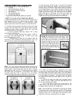
3) The entire main landing gear assembly is now mounted onto
the bottom of the fuselage using the three M4 x 15mm PWA
Mounting Bolts provided. Be sure to put a drop of thread locking
compound, such as Locktite
®
, on the threads of the bolts before
screwing them in.
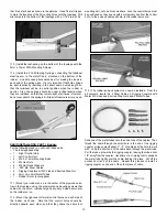
FUSELAGE ASSEMBLY, PART III: Cowling and Spinner:
For the following steps you will need these parts:
•
The fuselage assembly
•
1 - Fiberglass Cowling
•
4 - M2.6 x 10mm PWA Mounting Screws
•
1 - 2-3/4” Spinner Assembly*
* The plastic spinner assembly included in this kit should work fine in most
cases. However with the Saito .91 engine and APC prop combination
shown in our photo model, we decided to use an aftermarket aluminum
spinner.
The Saito's crankshaft was not long enough to go through
FUSELAGE ASSEMBLY, PART II: Main Landing Gear
For the following steps you will need these parts:
•
The fuselage assembly
•
1 - Aluminum Landing Gear
•
3 - M4 x 15mm PWA Mounting Bolts
•
2 - 2-3/4" dia. Main Wheels
•
2 - M4 x 34mm PWA Axle Bolts
•
2 - M4 Lock Nuts
•
4 - M4 Hex Nuts
•
1 - Right Fiberglass Wheel Pant
•
1 - Left Fiberglass Wheel Pant
•
4 - M3 x 10mm PWA Mounting Bolts
•
4 - M3 Split Lock Washers
Note: When assembling the hardware in the following steps, we
recommend that you use a thread-locking compound, such as
Locktite
®
, to keep the parts from vibrating loose in flight. It only
takes a small drop, placed right in the threads of the mating parts,
to keep them tight and secure.
❑
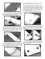
1) a. Insert one of the M4 x 34mm PWA Axle Bolts through the
hub of one of the 2-3/4” dia. Main Wheels. Slide the wheel all the
way up against the head of the bolt.
b. Next thread a M4 Hex Nut onto the threaded end of the
bolt, and run it all the way up to the wheel - but not too tight - the
wheel must turn freely.
c. Now thread another M4 Hex Nut up tight against the first
one. This extra hex nut serves as a spacer to keep the tire from
rubbing on the wheel pant after it is installed.
d. Finally, insert the threaded end of the axel bolt through
the aluminum landing gear leg and install an M4 Lock Nut. Tighten
securely.
e. Repeat this proceedure to install the other wheel onto the
opposite landing gear leg.
❑
2) Mounts the Fiberglass Wheel Pants to the landing gear with
the M3 x 10mm PWA Mounting Bolts and M3 Split Lock Washers
9
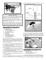
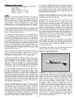
IMPORTANT SAFETY ISSUE!
DO NOT DRILL AND TAP THE GLASS-FILLED ENGINE MOUNTS
FOR BOLTS, OR USE SELF-TAPPING SCREWS OR WOOD
SCREWS.
THOSE METHODS WILL WEAKEN THE ENGINE
MOUNTS AND CAN LEAD TO ENGINE MOUNT FAILURE!
1) Use only Socket-Head Bolts with Aircraft Lock Nuts and Flat
Metal Washers to fasten your engine to the glass-filled engine
mounts, as shown in these instructions.
2) The holes you drill through the mounts must be big enough for the
engine mounting bolts to pass freely through. The bolts should not go
in tight. In the case of 8-32 mounting bolts, a 11/64" dia. drill bit will
provide proper clearance holes. For 10-32 bolts use a 13/64” drill bit.
provided. Tighten securely. Double check to make sure that the
wheels turn freely without obstruction.