


16
RADIO INSTALLATION, PART IV: Radio System:
With all the servos now installed, all that remains is the installation
of the receiver, battery pack, and switch.
RX BATTERY PACK: The single heaviest unit of the radio system
is the battery pack. This means that you can, if needed, locate the
battery pack wherever it is needed in the airplane to help achieve
the correct balance point. Be sure to wrap the battery pack in foam
rubber and use rubber bands or tie-wraps to secure it to the model
structure so that it can't move around in flight.
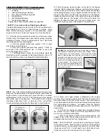
RECEIVER: Wrap the receiver in foam and use rubber bands or
tie-wraps to secure it in the fuselage. Notice that the MAYHEM has
a plastic tube already installed inside the fuselage for use as an
internal antenna mount.
The plastic tube runs from the radio
compartment all the way back through the fuselage, with an exit
hole in the bottom of the fuse just ahead of the tailwheel assembly.
Slide your antenna into this tube when installing your receiver.
Note: Instead of trying to push the limp antenna wire all the way
through the plastic tube, its easier to run a long small diameter
music wire (not supplied) from the back of the airplane, into the
tube, and forward into the radio compartment. When the music
wire appears inside the fuselage, tape the end of your antenna to
it, and then slowly pull the antenna out to the back of the airplane.
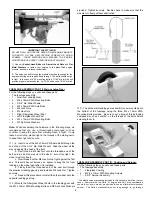
SWITCH:
The radio on/off switch should be mounted on the
fuselage side opposite the engine exhaust. Cut a small rectangular
opening in the fuselage side for the switch toggle to poke through,
and drill two small holes for the switch mounting bolts.
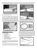
SAFETY CHECK: The elevator and aileron pushrods have spring
keepers to prevent the R/C links from opening up in flight, while the
rudder and throttle R/C links do not. Take the time to fit each
rudder and throttle R/C link with a short length of silicone fuel
tubing to keep the links firmly closed. This common safety practice
has saved a lot of models! Also, make sure that you have secured
the servo arms to each servo with the retaining screws.
Turn the radio system on and check the functions of all the
controls.
Make sure they are moving in the right direction!
Thousands of R/C airplanes have crashed over the years because
the servos were moving the wrong way! Also make sure all the
servos are centered and working perfectly, without any binding.
Correct any such problems now, before proceeding.
RADIO INSTALLATION, PART V: Set The Control Throws:
Use a ruler to accurately measure and adjust the travel of each
control surface to the amounts shown below. Keep in mind that
these settings are meant to serve as a starting point. As you gain
experience flying your MAYHEM, you may want to adjust the
throws to suit your flying style. All measurements should be taken
at the widest part of the elevators, ailerons, and rudder.
RADIO INSTALLATION, PART VI: Range Check:
Be sure to range check your radio installation on the ground,
before you attempt to fly your MAYHEM for the first time. With the
transmitter antenna collapsed, and the receiver and transmitter
turned on, you should be able to walk at least 100 ft. away from the
model and still have solid control. Have an assistant stand by the
airplane to watch the action of the control surfaces, while you walk
slowly away from the model, constantly working the controls as you
go. Your assistant should signal to you if the control surfaces
become erratic. If all is well out to 100 ft. or further, repeat the test
with the engine running, with the assistant holding the airplane. If
the control surfaces do not respond correctly, do not fly! Find and
correct the problem first.
Look for loose servo connections or
broken wires, corroded wires, poor solder joints in your battery
pack, or a defective cell in the battery pack, or a damaged
receiver crystal from a previous crash. If you can’t find and fix the
problem, send the radio in to an approved service center.
NEVER FLY WITH A RADIO SYSTEM THAT ISN’T WORKING
100% CORRECTLY. THE PROBLEM WON’T GET BETTER IN
THE AIR, IT WILL GET WORSE!
Normal Control Throws
High Rate
Low Rate
Elevator
1-3/4" up
1-1/4" up
1-3/4" down
1-1/4" down
Ailerons
1-1/2" up
1" up
1-1/2" down
1" down
Rudder
3" right
2" right
3" left
2" left
3D Control Throws
The 3D control throws are only meant for
extreme aerobatics. They are not meant for
normal flying. You should be competent and
comfortable flying your MAYHEM with normal
control throws before attempting 3D rates.
Elevator:
2-3/4" up
2-3/4" down
Ailerons:
2-1/4" up
2-1/4" down
Rudder:
4-1/2" right
4-1/2" left
Expo:
Use -20% exponential travel on elevator,
ailerons, and rudder when using 3D rates.