


❑
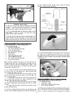
4) Determine the location of the hole required in the cowling for
access to your engine's needle valve. Start with the engine and
cowling on the airplane and “eyeball” the approximate location of
where the needle valve will exit the cowling. Take your best guess
and mark that location on the cowl. Now make a small 1/16” dia.
hole at the marked location. Chances are that you are close to
the correct spot. Stick a piece of music wire into the hole, down to
the needle valve.
Carefully observe if the hole needs to be
repositioned to straighten up the wire, as if it were the needle valve.
Make another mark on the cowl and open the hole just a little
towards the corrected position. In this manner, continue checking
and adjusting the exit hole until it aligns perfectly with the
carburetor/needle valve position. Then enlarge the hole enough to
insert and install the needle valve in the carb. Be sure the hole has
at least 3/32" clearance around the needle valve to avoid contact.
Tip: A handy tool to assit with cutting holes in the cowling is a
small penlight. The penlight can be used from the inside or outside
of the cowl to highlight and spot the required hole location.
❑
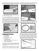
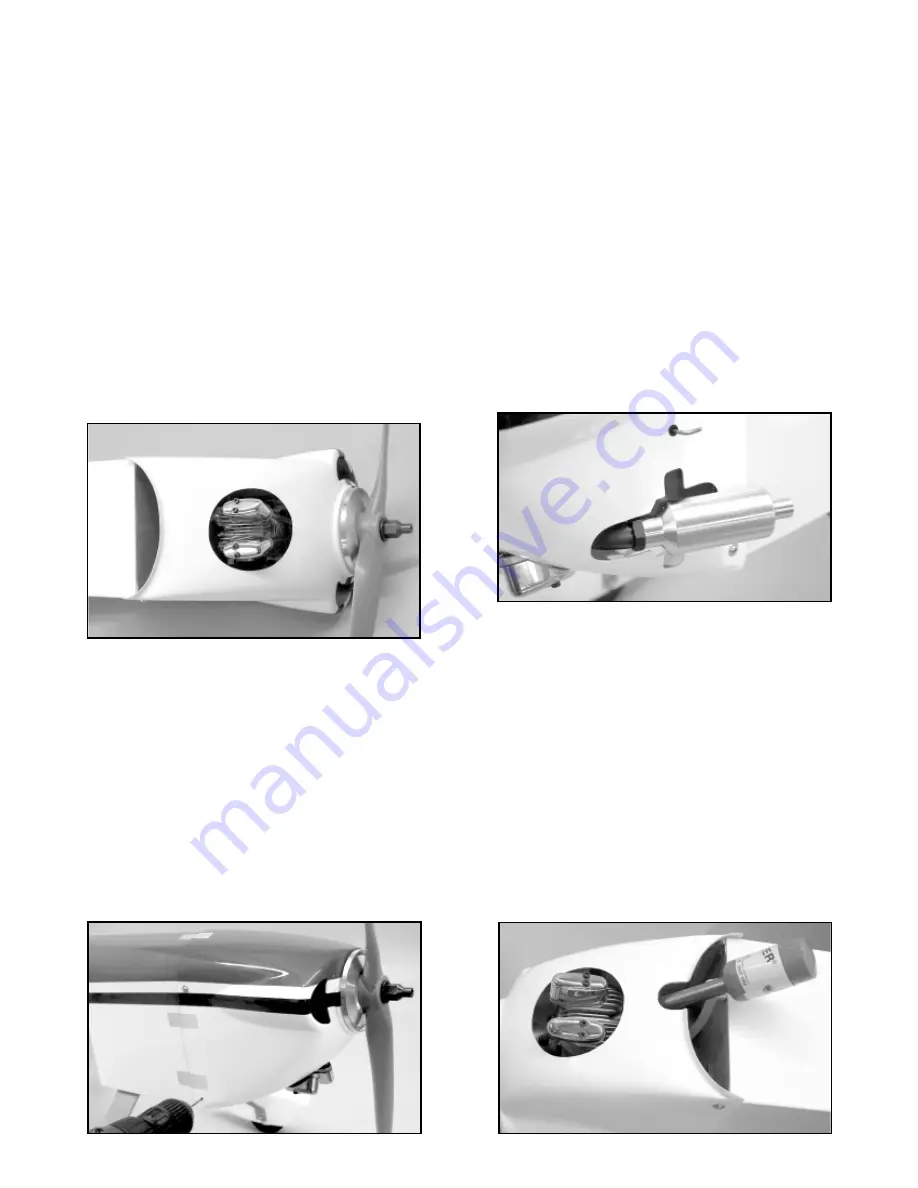
5) Figure out what size and shape opening you will need in the
cowling to accomodate your engine’s muffler, and cut it out now.
Note: As you can see in the photo, the cutout for the Saito .91
muffler in our photo model was a bit of a challenge. Thru visual trial
and error we determined that it would be best to install the muffler
level. The next step was to remove the cowling from the airplane
and permanently mount the “pipe” portion of the muffler assembly
on the engine in the level position. Then a cutout was made in the
cowling to clear the pipe, so that the cowling could be reinstalled on
the fuselage.
Next the cutout was gradually enlarged until the
“chamber” portion of the muffler could be screwed onto the end of
the pipe. Undoubtably there are other ways this muffler installation
could be done. You may have other ideas.
❑
6) Figure out how you are going to light your glow plug and
whether that will require an opening in your cowling.
Note: One option, that requires no cowling changes, would be to
use a “remote” glow plug wiring harness, (not supplied). Another
option, as shown here with our Saito .91 installation, was to use an
the spinner backplate, through the thick APC prop, and still have enough
threads sticking out in front of the prop to safely use the standard Saito
prop nut and washer. We found that a TrueTurn
®
aluminum spinner had a
thinner backplate and a different style prop nut, which took care of the
problem. Depending on your engine and prop combination, you might face
a similar situation. Another alternative to a whole new spinner would be to
find a prop nut that extends down into the prop hub, like some of the older
OS
®
4-stroke prop nuts.
❑
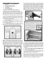
1) Try fitting the Fiberglass Cowling over your engine and back
onto the fuselage.
If you have a typical MAYHEM engine
installation (meaning a single-cylinder engine mounted inverted)
you will need to make an opening in the bottom of the cowling for
the engine cylinder to stick through. Watch carefully to see where
the head of the engine first hits the inside of the cowling and mark
that location with a pencil or felt tip marker. Remove the cowl, and
use a Dremel
®
Tool to make a small opening in the cowl at the point
of contact. Refit the cowl, checking the hole location and size,
adjust as needed and again use the Dremel
®
Tool to make the
opening bigger. Keep refitting, remarking and readjusting the hole
until the cowling can be slipped over the engine into correct
position on the fuselage. As a general rule, you should end up with
at least 3/16" clearance between the cowling and any engine part.
❑
2) Once the cowling is in place without any part of the engine
contacting it, mount your spinner backplate and propeller on the
engine prop shaft. Tighten the prop assembly sufficiently to bring
the spinner backplate firmly in contact against the engine’s prop
mounting flange. Now check to see that you have at least a 1/16"
gap between the back of the spinner backplate and the front of the
cowling (1/16” to 1/8” is OK).
Adjust the final location of the
cowling, making sure that the spinner backplate is centered on the
front and that the back edges are tight against the fuselage. Use
masking tape to temporarily hold the cowling in correct position on
the fuselage.
❑
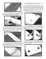
3) With the cowling securely taped in place, use a 3/64" (or
#56) dia. drill bit to drill pilot holes in the fuselage, centered in each
of the four pre-drilled mounting holes in the cowl. Mount the cowl
to the fuselage with the four M2.6 x 10mm PWA Screws provided.
10