


mounting bolt, nuts, and lock washers. Also, the control horns must
be positioned so they line up with an imaginary line from the control
horn, to the pull-pull cable exit hole, to the rudder servo arm.
❑
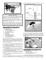
3) The rudder pull-pull system can now be installed. From the
kit contents, locate the 2 Steel Cables, 4 Rigging Couplers with
Metal R/C Links and Knurled Stop Nuts, and 4 Metal Tubes.
Slide one of the metal tubes onto the end of one of the cables. Then
thread the cable through the small hole in the end of the rigging
coupler, giving yourself about 4" - 5" of cable past the hole to work
with. Loop the short end of the cable back through the metal tube.
Pull the tube up towards the rigging coupler, leaving the tube about
1/2" away from the coupler. Use pliers or a crimping tool to squeeze
the metal tube tightly over the cable, locking it in place. Cut off the
excess short end of the cable. Repeat this process to install a
rigging coupler on one end of the other piece of cable.
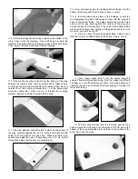
that it is as far back as shown in the pictures. Use a fine felt-tip pen
to mark the locations of the 3 mounting holes onto the fuselage. Drill
pilot holes into the bottom of the fuselage with a 1/16" dia. drill bit.
❑
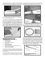
3) Install the leaf-spring on the bottom of the fuselage with the
3mm x 10mm PWA Mounting Screws.
❑
4) Install the 2 Coil Steering Springs, connecting the tailwheel
steering arm to the metal T-horn mounted on the bottom of the
rudder. A needle nose pliers works best for making the loops in
each end of the spring wires. It’s very important that both springs
be bent identically, resulting in the exact same overall length, so
that the tailwheel will be in neutral position when the rudder is
neutral. Also, the springs should be under a little tension when
they are installed, so that they remain tight at all times. However,
do not over stretch the springs. A little bit of tension is all you need.
RADIO INSTALLATION, PART I: Rudder:
For the following steps you will need these parts:
•
The fuselage assembly
•
1 - Right Control Horn
•
1 - Left Control Horn
•
4 - M2.5 x 14mm Mounting Bolts
•
4 - M2 Hex Nuts
•
4 - M2 Split Lock Washers
•
2 - .023” dia. Steel Cables
•
4 - Rigging Couplers w/ R/C Link and Knurled Stop Nut
•
2 - 2mm od x 4mm Metal Tubes
•
1 - Rudder Servo (not supplied)
❑
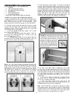
1) Mount your rudder servo in the center of the plywood servo
tray in the fuselage, using the grommets and mounting screws that
came with the servo. Install a large heavy-duty 2-sided servo arm
on the rudder servo.
❑
2) Mount the right and left metal control horns on each side of
the rudder, as shown.
Note that the control horns should be
directly opposite each other, and that they share the same four
13