


❑
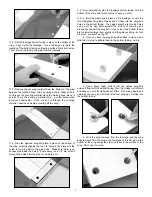
4) The finished ends of the two cables prepared in the last step,
are for hooking up to the rudder control horns. Feed the unfinished
bare ends of the cables into the pull-pull exits built into the rear of
the fuselage, one on each side. Pass the cable ends completely
through the rear of the fuselage and up to the rudder servo loca-
tion.
Keep pulling the cables forward until you can
connect the R/C links to the rudder control horns.
❑
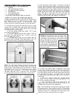
5) Turn the fuselage upside down on your bench to make it eas-
ier to complete the pull-pull cable connections to the rudder servo
arm.
a. Temporarily plug your rudder servo into your receiver and
turn on the radio system. Make sure the rudder trim lever on the
transmitter is centered. Then center the servo arm on the rudder
servo. Temporarily tape the rudder in neutral alignment with the fin.
b. Examine the two remaining rigging couplers and center the
R/C links on the threaded portions of the couplers. Clip the R/C
links into the outermost holes at each end of the rudder servo arm.
d. Pick up the bare end of one of the pull-pull cables inside the
fuselage and lightly pull on it, while you look inside the fuselage to
make sure the cable is not caught on or twisted around anything.
Then slide one of the remaining metal tubes over the end of that
cable. Next, poke the end of the cable through the small hole in the
end of the appropriate rigging coupler on the rudder servo arm
(make sure you’re installing the left side cable in the left side
rigging coupler, and vice versa). Make a half loop back into and
through the metal tube. Pull the cable snug to remove any slack
(not too tight) as you slide the metal tube up close to the servo
arm. Crimp the tubing tightly over the cable, locking it in place. Cut
off the excess short end of the cable. Repeat the process to attach
the other pull-pull cable on the opposite side of the servo arm.
❑
6) With the rudder still taped in neutral position, adjust the
threaded R/C links until you get both pull-pull cables to
approximately the same mild tension - it’s not necessary to pull the
cables extremely tight. Remove the tape holding the rudder in
place, turn on the transmitter and test the movement and centering
of the rudder. Adjust as needed. When satisfied with the operation
of the pull-pull system, tighten the knurled stop nut on each rigging
coupler up against the end of the R/C link to lock the links in place.
14
RADIO INSTALLATION, PART II: Elevator:
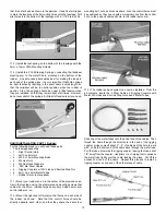
For the following steps you will need these parts:
•
The fuselage assembly
•
1 - 4-40 x 3” Threaded Pushrod
•
2 - 4-40 Metal R/C Links
•
2 - 4-40 Hex Nuts
•
2 - Spring Keepers
•
1 - Right Control Horn
•
4 - 2.6mm x 10mm Mounting Screws
•
1 - Elevator Servo (not supplied)
•
1 - 24” Servo Extension Chord (not supplied)
❑
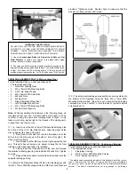
1) Plug a 24” long servo extension chord onto the end of the
elevator servo wire. Secure well with tape. Poke the free end of
the extended servo wire through the elevator servo mount in the
rear of the fuselage. Hold the fuselage vertically as you pass the
servo wire all the way forward to the radio compartment. Avoid
tangling the servo wire with the rudder pull-pull cables. Once you
have the wire completely inside, install the elevator servo in the
fuselage using the using the rubber grommets and screws that
came with the servo.
❑
2) Mount the control horn on the bottom of the right elevator
using the four 2.6mm x 10mm mounting screws. Locate the horn
near the end of the elevator, directly in line with the elevator servo
(there is a plywood plate to mount the horn on, already built into
the bottom of the elevator, under the covering material). Hold the
control horn in place on the elevator, lined up with the elevator
servo arm. Also make sure the pivot holes in the control horn line
up with the hinge line. Mark the four control horn mounting holes
on the elevator with a felt-tip pen. Drill a 3.64” dia. (or #56 drill) pilot
hole for each screw, then screw the horn in place.
❑
3) The elevator pushrod consists of a Threaded Rod with a Hex
Nut, a R/C Link, and a Spring Keeper on each end. Clip one end
of the pushrod into the elevator servo arm. Clip the other end of
the pushrod into the control horn. Adjust the overall length of the
pushrod by screwing the R/C links in or out as needed to get the
elevator in neutral position when the servo is neutral. Once you
have the pushrod length properly adjusted, slide the spring
keepers up onto the R/C links, and then screw the hex nuts up tight
against the end of the R/C links. Put a drop of Locktite
®
thread
locking compound, or CA glue, on the hex nuts to keep them from
coming loose.
IMPORTANT: After you finish mounting the control horn on
the elevator for the first time, take it back off and set it aside.
Then put a few drops of Thin CA into each of the four
mounting screw holes in the elevator. The Thin CA will soak
into the threads in the wood, and when it dries the holding
power of the threads will be much stronger. Use Thin CA only,
not medium or thick CA.
Let the Thin CA dry completely
before remounting the control horn onto the elevator.