


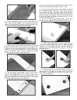


5
to clean up all the glue smears with a paper towel soaked in
rubbing alcohol. Also, if possible get someone to help you with this
proceedure. An extra set of hands makes the job much easier!
While one person is holding the wing panes tightly together, the
other person can wipe off the excess glue.
WING ASSEMBLY, PART III: Hinging the ailerons:
For the following steps you will need these parts:
•
The wing assembly
•
1 - Right Aileron
•
1 - Left Aileron
•
12 - CA Hinges (6 per aileron)
❑
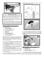
1) Start by reinserting the CA Hinges back into the six slots in
the trailing edge of the wing panel. Slide the hinges HALFWAY into
each hinge slot. DO NOT GLUE THE HINGES AT THIS TIME!
❑
2) Now reinstall the aileron onto the exposed half of the hinges.
It's easiest to slip the aileron onto the hinges at angle, one hinge
at a time, instead of trying to push it straight onto all the hinges at
once. Start at the wingtip, inserting the end hinge into the end slot
in the aileron. Once you have that hinge started, move to the next
hinge and get it started into its slot. Move on down the line until
you have all six hinges started.
Then you can finish
pushing the aileron up against the back of the wing. Don't be
overly concerned if the hinges don't end up perfectly straight or
perfectly centered in the slots - approximately halfway is good
enough. AGAIN, DO NOT GLUE THE HINGES IN AT THIS TIME!
❑
3) To set the proper amount of gap between the aileron and the
wing, simply deflect the aileron to the maximum amount of travel
needed. This will automatically set the proper hinge gap! Keep in
mind that for best control response the gap should be kept as small
as possible, but big enough to allow full movement of the control
surface. Make sure everything is functioning properly before pro-
ceeding to the next step.
❑
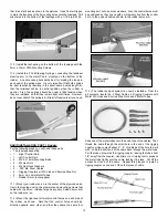
4) Flex the aileron downward, exposing the hinges between the
wing and aileron.
Carefully place 3-4 drops of Thin CA glue
directly onto each hinge in the gap. You will notice that the glue is
quickly wicked into the slot as it penetrates both the wood and the
hinge. Turn the part over and apply 3-4 drops of glue to the other
side of each hinge. Keep a rag handy to wipe off any excess glue.
Note:
For CA hinges, we always recommend using a fine-tip
applicator on your CA glue bottle, to better control the flow. Also,
if you get some glue smears on the plastic covering, don't worry
about them right now. Once the glue has had a chance to dry, you
can clean the glue smears off the covering with CA Debonder.
❑
5) Allow at least 10 minutes before flexing the aileron. After suf-
ficient time has passed, flex the aileron up and down several times.
At first you might notice a little stiffness in the joint. This will go
away after the hinges have been flexed back and forth a few times.
Also, pull on the aileron at each hinge location to make sure all the
hinges are securely in place. Repeat this process to attach the
other aileron to the other wing.
WARNING: The CA hinges provided in this kit are made of a
special absorbant material that can only be glued with Thin CA
adhesive. Thin CA (any brand) is the ONLY type of glue that can
be used on these hinges - do not use epoxy or any other type of
glue! Also, never use CA Accelerator on CA Hinges!
It's critical that you only make one application of glue to each side
of a CA Hinge! If you apply additional glue after the first
application of glue is dry, the second application of glue will
merely puddle in the hinge gap and make the hinge too stiff to
operate. The excess glue could also weaken the hinge! When
properly glued, the part of the hinge that you can see in the hinge
gap should have a dry appearance, not wet. A dry appearance
indicates that almost all of the glue has properly soaked into the
hinge slot.
A wet appearance indicates that excess glue is
puddled in the hinge gap. Three to four drops of Thin CA is the
right amount.
WING ASSEMBLY, PART IV: Install Control Horns & Pushrods:
For the following steps you will need these parts:
•
The wing assembly
•
2 - 4-40 x 3” Threaded Pushrods
•
4 - 4-40 Metal R/C Links
•
4 - 4-40 Hex Nuts
•
4 - Spring Keepers
•
1 - Right Control Horn
•
1 - Left Control Horn
•
8 - 2.6mm x 10mm Mounting Screws
•
2 - Aileron Servos (not supplied)
•
2 - Heavy-Duty Servo Arms (not supplied)
❑
1) Install heavy-duty servo output arms on the aileron servos.
For 3D flying, the servo arms should be at least 3/4” long to
provide full control surface travel. Install the arms on the servos
with the arms pointing towards the wing tips, not towards the
fuselage. Also make sure the arms are 90
O
to the servo when the
transmitter’s aileron control stick and trim lever are both in neutral.