SIG 3D MAYHEM ARF Assembly Manual Download Page 17

17

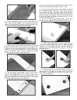
4) A 3/8” x 1/2” x 4” balsa stick is provided to keep the fuel tank

in place. Install the balsa stick across the back of the tank, gluing
it to the front of the fuselage former. This will keep the tank from
sliding backwards in flight. If the tank ever has to be removed for
service, you can break the balsa stick loose and get the tank out.

DECAL APPLICATION:
The decals in this kit are made of sticky-back mylar with an
extremely aggressive adhesive. They are NOT water activated
transfers. These decals are not die-cut and need to be cut from
their sheets with a sharp hobby knife or scissors. Trim as close to
the image as possible.

Putting sticky-back decals on a model can be tricky!  Especially
medium to large size ones like those in this kit. If you don't do it
right you will end up with unsightly air bubbles trapped underneath
the decal. The best method is to put large decals on “wet”.

You will need a "soapy water" mixture (water mixed with a very
small amount of dish soap, or SIG Pure Magic Model Airplane
Cleaner, or Fantastic

®

, Windex

®

, or 409

®

type cleaners all work

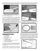
good). You will also need a supple squeegee, (the SIG 4" Epoxy
Spreader  #SIGSH678 is perfect for this job), a couple clean soft
cloths (old tee shirts are great), a good straight edge, a ruler, and
a hobby knife with sharp #11 blades. We also suggest that you
have some trim tape handy for making temporary guidelines (1/8"
width or so is perfect) for help in aligning the decals.

First spray the surface of the model where the decal is to be placed
with a soapy water mixture.

Then peel the backing sheet 

completely off the decal, being careful not to let the sticky side 
double over and adhere to itself. Place the decal onto the wet 
surface of the model.

Do not push down!  The soapy water 

solution will keep the decal from actually sticking to the model until
you have had time to shift it around into exact position. Once you
have it in position, squeegee the excess soapy water out from
under the decal. Mop up the water with a dry cloth. Squeegee
repeatedly to get as much of the water out from under the decal as
possible. After setting overnight, the decal will be solidly adhered
to the surface.

FUEL TANK INSTALLATION

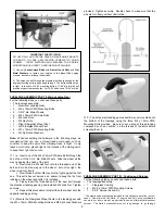
1) Assemble the fuel tank as shown. We recommend that you

plumb your tank with a standard 2 tube setup, with or without the
optional aftermarket fueling valve (see page 11, step 7). One of
the tubes is the “vent” line, through which you will fuel and defuel
the tank. The other tube is the “fuel feed” line to the carburetor.

Note that the rubber stopper for the tank has two holes that go all
the way through it. Use these holes for the aluminum vent and fuel
feed tubes. Use the shortest of the three supplied aluminum tubes
for the fuel feed tube. Use the longest of the aluminum tubes for
the vent tube. Gently bend the vent tube upwards to 90

O

, so it will

be near the top of the tank.

Adjust the length of the internal 

silicone fuel tubing to allow free movement of the metal clunk 
pick-up inside the tank. Install the stopper assembly into the neck
of the tank and secure by tightening the clamp bolt.

Be sure to label the "vent" and "carb" lines for later identification.

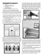
2) Trial fit the tank in place into the front of the fuselage to 

familiarize yourself with how it mounts. The front of the tank should
fit through the hole in the firewall. The main body of the tank is 
supported by the contoured hole in the fuselage former. Take the
tank back out of the fuselage.

3) Apply a bead of silicon adhesive around the neck of the tank,

where it will contact the inside of the firewall. Put another big blob
of silicone on the front of the tank just below the neck. Slide the
tank in place into the fuselage, pushing it in until the neck goes into
the hole in the firewall. Do not push it all the way up tight against
the firewall. Leave it about 1/8" short. The blob of silicone on the
front of the tank will act as a spacer and cushion between the tank
and the firewall after it dries. It will also keep the tank away from
the ends of the engine mounting bolts that may be protruding
slightly past the back of the firewall.

Summary of Contents for 3D MAYHEM ARF

Page 1: ... glues thin medium and thick SIG CA and SIG Epoxy Glue 5 minute and 30 minute R 1 3D MAYHEM ARF ASSEMBLY MANUAL INTRODUCTION Congratulations on your purchase of a SIG 3D MAYHEM ARF This is not your average R C aerobatic flyer Properly assembled powered and flown the 3D MAYHEM can take you into the exciting world of 3D aerobatic flying Generous wing area lightweight construction and huge control su...

Page 2: ...4mm PWA Axle Bolts 2 M4 Lock Nuts 4 M4 Hex Nuts 2 2 3 4 dia Main Wheels 4 M3 x 10mm PWA Mounting Bolts for wheel pants 4 M3 Split Lock Washers for wheel pants 1 bag Tailwheel Assembly 1 Leaf Spring with Steering Arm Yoke Tailwheel 3 3mm x 10mm PWA Mounting Screws 2 Coil Steering Springs 1 Metal Rudder T Horn 2 2mm x 9mm PWA Mounting Screws for T Horn 1 bag Fuel Tank Assembly 1 450cc 15 2 oz Plasti...

Page 3: ... warp The amount of reverse twist and heat that you apply will determine where the control surface ends up after it cools Note When trying to remove a warp an extra set of hands are needed Have someone assist you While one person holds the reverse twist in the control surface the other person applies the heat by passing a covering iron over both sides of the part WING ASSEMBLY OVERVIEW The wing of...

Page 4: ...y in place on the servo mount Repeat this proceedure to mount the servo in the opposite wing panel WING ASSEMBLY PART II Joining the wing panels For the following steps you will need these parts 1 Right Wing Panel 1 Left Wing Panel 1 Hardwood Wing Joiner 1 Trial fit both wing panels onto the Hardwood Wing Joiner Check to see that the wing panels fit together in proper alignment and that both root ...

Page 5: ... recommend using a fine tip applicator on your CA glue bottle to better control the flow Also if you get some glue smears on the plastic covering don t worry about them right now Once the glue has had a chance to dry you can clean the glue smears off the covering with CA Debonder 5 Allow at least 10 minutes before flexing the aileron After suf ficient time has passed flex the aileron up and down s...

Page 6: ...g 2 We need to draw guidelines on the ailerons to show where to mount the control horns a First draw a line paralell to the aileron hinge line right at the back edge of the aileron leading edge Note If you reflect light off the aileron covering you can clearly see the back edge of the aileron leading edge This piece is balsa wood Right behind this leading edge balsa is a piece of hardwood approxim...

Page 7: ...m fairing d With the wing removed from the fuselage and the wing bolts removed from the wing put a few drops of thin CA glue in the bottom of the wing bolt guides to bond them to the surface of the wing Don t use too much 7 2 Set the fuselage bottom fairing in place on the bottom of the wing Align it with the fuselage Use a felt tip pen to mark the location of the bottom fairing on the wing surfac...

Page 8: ... M4 Split Lock Washers Engine and suitable Mounting Bolts not supplied SAFETY Size Limit on Glass Filled Engine Mounts The glass filled engine mounts provided in this kit are intended for glow engines up to 1 20 cu in either 2 stroke or 4 stroke Using these mounts with larger engines is not recommended Larger engines should use an aluminum engine mount not furnished 1 Note that the horizontal and ...

Page 9: ...ecure 1 a Insert one of the M4 x 34mm PWA Axle Bolts through the hub of one of the 2 3 4 dia Main Wheels Slide the wheel all the way up against the head of the bolt b Next thread a M4 Hex Nut onto the threaded end of the bolt and run it all the way up to the wheel but not too tight the wheel must turn freely c Now thread another M4 Hex Nut up tight against the first one This extra hex nut serves a...

Page 10: ...ther option as shown here with our Saito 91 installation was to use an the spinner backplate through the thick APC prop and still have enough threads sticking out in front of the prop to safely use the standard Saito prop nut and washer We found that a TrueTurn aluminum spinner had a thinner backplate and a different style prop nut which took care of the problem Depending on your engine and prop c...

Page 11: ... edge tip and note the distance Then make the same measurement on the opposite side of the airplane The two measurements must be the same Adjust the stabilizer as needed until they are the same 4 Once you have the stabilizer properly aligned use a felt tip pen to mark the locaton of the fuselage sides on the bottom and top of the stab Take the stabilizer off the airplane and remove the covering ma...

Page 12: ... place on the fuselage Make sure it is lined up with the fuselage centerline and 12 wood to wood joint between the stab and the fuselage in the next step Be very careful not to cut into the balsa wood when removing the covering material 5 The stabilizer elevator assembly can now be permanently glued into the fuselage Slow drying epoxy glue is recommended for this step to allow you plenty of time t...

Page 13: ...g on the bottom of the fuselage with the 3mm x 10mm PWA Mounting Screws 4 Install the 2 Coil Steering Springs connecting the tailwheel steering arm to the metal T horn mounted on the bottom of the rudder A needle nose pliers works best for making the loops in each end of the spring wires It s very important that both springs be bent identically resulting in the exact same overall length so that th...

Page 14: ...DIO INSTALLATION PART II Elevator For the following steps you will need these parts The fuselage assembly 1 4 40 x 3 Threaded Pushrod 2 4 40 Metal R C Links 2 4 40 Hex Nuts 2 Spring Keepers 1 Right Control Horn 4 2 6mm x 10mm Mounting Screws 1 Elevator Servo not supplied 1 24 Servo Extension Chord not supplied 1 Plug a 24 long servo extension chord onto the end of the elevator servo wire Secure we...

Page 15: ...4 Determine how long the pushrod sleeve needs to be to fit your installation we purposely provided it too long so it would cover most situations In most cases you will need to shorten the pushrod sleeve a little bit As a general rule the ends of the pushrod sleeve should be about 1 1 2 away from the servo arm and the throttle arm Use a sharp razor blade to cut the pushrod sleeve to length Remove t...

Page 16: ...lanes have crashed over the years because the servos were moving the wrong way Also make sure all the servos are centered and working perfectly without any binding Correct any such problems now before proceeding RADIO INSTALLATION PART V Set The Control Throws Use a ruler to accurately measure and adjust the travel of each control surface to the amounts shown below Keep in mind that these settings...

Page 17: ...om under the decal Mop up the water with a dry cloth Squeegee repeatedly to get as much of the water out from under the decal as possible After setting overnight the decal will be solidly adhered to the surface FUEL TANK INSTALLATION 1 Assemble the fuel tank as shown We recommend that you plumb your tank with a standard 2 tube setup with or without the optional aftermarket fueling valve see page 1...

Page 18: ...should hang level in side view With the model secured in this way level the wings and then slowly let go Ideally the wings should stay level when you put them there If one wing panel drops lower it means that it is heavier than the other panel When flying the model this imbalance can cause the airplane to pull to the heavy side especially in loops and up line maneuvers To make the airplane track t...

Page 19: ...d be a lot of fun Try to choose a calm day with little or no wind for the first flight Good conditions allow you to better evaluate and more accurately adjust the trim requirements for your airplane As we ve mentioned before a good running reliable engine is a must for the ultimate success of your airplane Take the time to solve any engine problems before you try to fly Always make it part of your...

Page 20: ...20 MAYHEM LOG BOOK Date of first flight Comments ...

Page 21: ...el size or full size are not toys Because of the speeds that airplanes must achieve in order to fly they are capable of causing serious bodily harm and property damage if they crash IT IS YOUR RESPONSIBILITY AND YOURS ALONE to assemble this model airplane correctly according to the plans and instructions to ground test the finished model before each flight to make sure it is completely airworthy a...

Page 22: ... to 91 2 Stroke 72 to 1 20 4 Stroke Wing Span 72 1 8 in 1830 mm Wing Area 1167 sq in 7529 sq cm Length 59 in 1500 mm Flying Weight 7 to 8 lb 3 2 to 3 6 kg Wing Loading 13 8 to 15 8 oz per sq ft Radio 4 channel with 5 servos 22 ...

Reviews: